


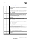
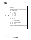
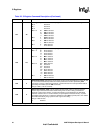
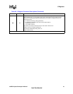
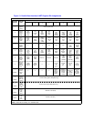
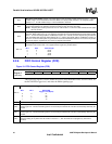
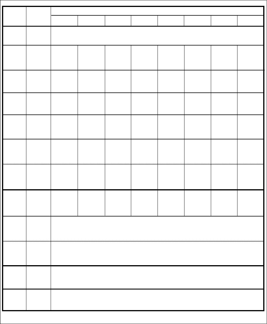
Figure 13. Parallel Host Interface UART Register Bit Assignments
NOTE: These bits are always ‘0’ in 16C450 mode.
REGISTER
NAME
REGISTER
ADDRESS
76543 210
BIT NUMBER
7
Scratch
register
(SCR)
DLAB=0
6
5
4
3
2
1
0
0
DLAB=0
DLAB=0
1
DLAB=1
0
DLAB=1
Divisor
Latch
(MS)
Divisor
Latch
(LS)
MS Divisor Latch (DLM)
LS Divisor Latch (DLL)
Receiver
Buffer
[read only]
Transmit
[write only]
Transmit Holding register (THR) [Write only]
Receiver Buffer register (RBR) [Read only]
Holding
register
Scratch register (SCR)
Modem
Status
register
(MSR)
Line
Status
register
(LSR)
Modem
Control
register
(MCR)
Line
Control
register
(LCR)
Interrupt
Identity
register
(IIR)
Interrupt
Enable
register
(IER)
(THR)
(RBR)
register
(DLL)
(DLM)
0
0
0
0
0
0
0
0
0
Data
Carrier
Detect
(DCD)
Ring
Indicator
(RI)
Data
Set
Ready
(DSR)
Clear
to
Send
(CTS)
Delta
Data
Carrier
Detect
(DDCDD)
Trailing
Edge of
Ring
Delta
Data
Set
Ready
(DDSR)
Indicator
(TERI)
Delta
Clear
to
Send
(DCTS)
Modem
Status
Interrupt
Enable
(MSIE)
Receiver
Line Status
Interrupt
Enable
(RLSIE)
Transmitter
Holding Reg.
Empty
Int. Enable
(THREIE)
Received
Data
Available
Int. Enable
(RDAIE)
Transmitter
Empty
(TEMT)
Transmitter
Holding
register
(THRE)
Break
Interrupt
(BI)
Framing
Error
(FE)
Parity
Error
(PE)
Overrun
Error
(OE)
Data
Ready
(DR)
Loop
Out 2
Out 1
Request
to
Send
(RTS)
Data
Terminal
Ready
(DTR)
Divisor
Latch
Access
bit
(DLAB)
Set
Break
Stick
Parity
Even
Parity
Select
Parity
Enable
(PEN)
Number
of
Stop bits
(STB)
(EPS)
Word
Length
Select
bit 1
(WLS1)
Word
Length
Select
bit 0
(WLS0)
Interrupt
ID
bit 1
Interrupt
ID
bit 0
‘0’ if
Interrupt
pending
FIFO
Control
register
[write only]
(FCR)
[read only]
RCVR
Trigger
(MSB)
RCVR
Trigger
(LSB)
Interrupt
ID
bit 2
(Note 1)
Reserved Reserved
Reserved
XMIT
FIFO
Reset
(XFIFOR)
RCVR
FIFO
Reset
(RFIFOR)
FIFO
Enable
(FIFOE)
2
FIFOs
Enabled
(Note 1)
FIFOs
Enabled
(Note 1)
Empty
(SPAR)
(SBRK)
Error in
RCVR
FIFO
(Note 1)