


136 Software Developer’s Manual
Power Management
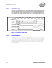
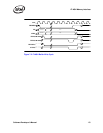
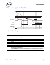
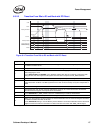
6.3.2.2 Transition From D0a to D3 and Back Without PCI Reset
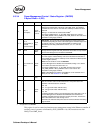
Figure 6-3. Transition from D0a to D3 and Back Without PCI Reset
I_PCI_CLK
RST#
PCI Pins
PWR_STATE[1:0]
Reading EEPROM
Read EEPROM
11b
11b
DState
D3 D0u D0
Wakeup Enabled
Memory Access Enable
Running
D3 write
APM onlyAny mode
D0 Write
D0a
3
1
00b if wakeup is disabled, 01b if wakeup is enabled
2
4
5
6
00b/01b
7
82544GC/EI Only
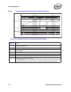
Diagram # Notes
1
Writing a 11b to the Power State field of the Power Management Control/Status Register (PMCSR) transitions
the Ethernet controller to D3.
2 The system can keep the Ethernet controller in D3 state for an arbitrary amount of time.
3
To exit D3 state the system writes 00b to the Power State field of the Power Management Control/Status
Register (PMCSR).
4 APM Wakeup mode can be enabled based on what is read in the EEPROM.
5 For the 82544GC/EI, PWR_STATE[1:0] is set to 01b if APM Wakeup is enabled, 00b otherwise.
6 The system can delay an arbitrary time before enabling memory access.
7
Writing a 1b to the Memory Access Enable or I/O Access Enable bit in the PCI Command Register transitions
the Ethernet controller from D0u to D0 state.
For the 82544GC/EI, writing a 1b to the Memory Access Enable or I/O Access Enable bit in the PCI Command
Register transitions the Ethernet controller from D0u to D0 state and asserts both PWR_STATE outputs.