


4Intel
®
NetStructure™ MPRTM4808 Rear Transition Board Installation Guide
Contents
5 Warranty Information..................................................................................................................... 30
5.1 Intel
®
NetStructure™ Compute Boards & Platform Products Limited Warranty................. 30
5.1.1 Returning a Defective Product (RMA) ................................................................... 30
6 Customer Support ......................................................................................................................... 33
6.1 Technical Support and Return for Service Assistance ....................................................... 33
6.2 Sales Assistance ................................................................................................................ 33
Figures
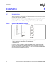
1 Location of IPMB1 and ICMB Connectors.................................................................................. 10
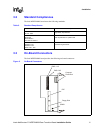
2 On-Board Connectors................................................................................................................. 11
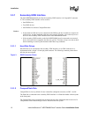
3 EIDE Connector Pinout .............................................................................................................. 12
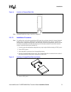
4 Location of CompactFlash Slot................................................................................................... 13
5 Inserting a CompactFlash Disk into Socket................................................................................13
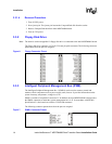
6 Floppy Connector Pinout ............................................................................................................ 14
7 IPMB1 Connector Pinout ............................................................................................................ 14
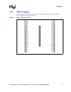
8 PMC 1 Connector Pinout............................................................................................................15
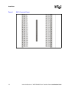
9 PMC 2 Connector Pinout............................................................................................................16
10 Location of Switches................................................................................................................... 17
11 Connecting Intel
®
NetStructure™ MPRTM4808 Rear Transition Board to Backplane............... 18
12 J3 Connector Pinout (Rows A-C) ............................................................................................... 19
13 J3 Connector Pinout (Rows D and E)......................................................................................... 20
14 J5 Connector Pinout (Rows A-C) ............................................................................................... 20
15 J5 Connector Pinout (Rows D and E)......................................................................................... 21
16 Front Panel Connectors and Controls ........................................................................................ 22
17 ICMB Connector Pinout.............................................................................................................. 23
18 PS/2 Keyboard/Mouse Connector Pinout................................................................................... 23
19 USB Connector Pinout ............................................................................................................... 24
20 COM Connector Pinout .............................................................................................................. 24
21 DB9 to RJ-45 Translation ........................................................................................................... 25
22 Reset Key ................................................................................................................................... 25
Tables
1 Terms and Definitions................................................................................................................... 6
2 Standard Compliances ............................................................................................................... 11
3 Switch Settings ........................................................................................................................... 17