


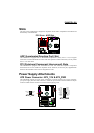
PX865PEL-800
12
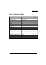
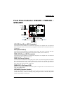
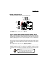
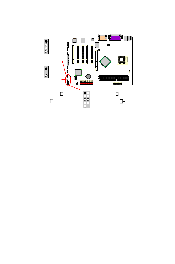
Front Panel Indicator: SW/LED、PWRLED、
SPEAKER
HD LED (Hard Drive LED Connector)
This connector can be attached to an LED on the front panel of a computer case. The LED will
flicker during disk activity. This disk activity only applies to those IDE drives directly attached to the
system board.
RST (Reset Button)
This connector can be attached to a momentary SPST switch. This switch is normally left open.
When closed it will cause the mainboard to reset and run the POST (Power On Self Test).
PWR-LED (Power LED Connector)
This connector can be attached to an LED on the front panel of a computer case. The LED will
illuminate while the computer is powered on.
PWR ON (Power Button)
This connector can be attached to a front panel power switch. The switch must pull the Power Button
pin to ground for at least 50 ms to signal the power supply to switch on or off (the time required is
due to internal debounce circuitry on the system board). At least two seconds must pass before the
power supply will recognize another on/off signal.
PWRLED (3-Pin Power LED )
If there is a 3-pin power LED cable on the front panel of a computer case. You can attach it to the
3-pin power LED connector.
SPEAKER (Speaker Header)
A front panel speaker can be connected to this connector. When you boot your computer, the speaker
sounds a short “beep”. If there is something wrong during the Power On Self-Test, the speaker
sounds “irregular beep” to warning you.
+
-
1
HD LED (+)
PC_BEEP
NC
Ground
+5V
Power LED (+)
Power LED (-)
Power Button (+)
Power Button (-)
NC
HD LED (-)
Reset Control (-)
Reset Control (+)
NC
9
2
10
1
1
2
2
3
3
4
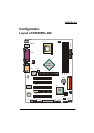
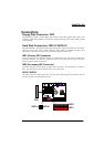
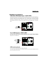
Intel
82865P
LAN
CHIP
Winbond
W83 627 HF
1
BIOS
1
2
1
2
2
2
11
9
10
Intel
ICH5
1
1
Socket 478
1
1
ALC
650
1
1
1
1
2
9
10
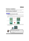
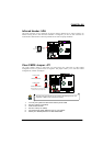
PWRLED
SPEAKER
SW/LED
1
Hard Driver
LED
Power
LED
Power-on
Button
Reset
Button