


18 Intel
®
Server System SR1550AL/SR1550ALSAS User’s Guide
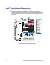
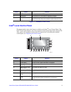
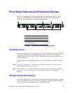
Figure 12. Intel
®
Local Control Panel
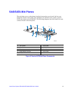
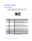
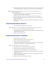
Bezels
The optional front bezels provide a snap-on design that allows for maximum airflow
through the server chassis. Two bezels are available. One fits a system that has the
standard control panel installed. The other is used for a chassis with the other Intel
®
Local
Control Panel. Each bezel provides a lock to secure the hard drive and optical drive area.
For instructions on installing either of the front bezels, see “Installing the Front Bezel”.
The order numbers for the bezels are:
• ADWBEZBLACK: Black bezel for use with the standard control panel.
• ADWLCDBEZEL: Black bezel for use with the Intel
®
Local Control Panel.
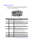
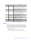
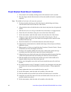
H. Power/Sleep LED Continuous green light indicates the system has power applied to
it.
Blinking green indicates the system is in S1 sleep state.
No light indicates the power is off / is in ACPI S4 or S5 state.
I. Power/Sleep Button Powers on/off the system.
Puts the system in an ACPI sleep state.
J. System Status LED Solid green indicates normal operation.
Blinking green indicates degraded performance.
Solid amber indicates a critical or non-recoverable condition.
Blinking amber indicates a non-critical condition.
No light indicates POST is running or the system is off.
K.
L.
NIC 2 Activity LED
NIC 1 Activity LED
Continuous green light indicates a link between the system and
the network to which it is connected.
Blinking green light indicates network activity.
M. Hard Disk Activity
LED
Random blinking green light indicates hard disk drive activity
(SAS or SATA).
No light indicates no hard disk drive activity.
N. Reset Button Reboots and initializes the system.
O. USB 2.0 Port Allows you to attach a USB component to the front of the system.
Callout Feature Function