


Intel
®
Server System SR1550AL/SR1550ALSAS User’s Guide 33
Note: Make sure the alignment triangle mark and the alignment triangle cutout align correctly.
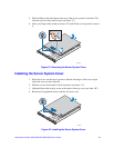
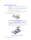
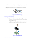
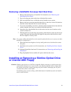
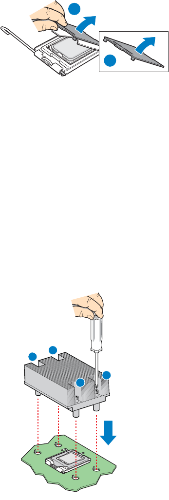
8. Remove the protective socket cover (see Figure 27).
Note: Retain the protective socket cover for use when removing a processor that will not be
replaced.
Figure 27. Removing the Socket Cover
9. Lower the CPU load plate and lower the socket lever completely.
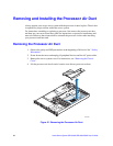
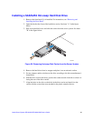
Installing the Heat Sink(s)
The heat sink has Thermal Interface Material (TIM) located on the bottom of it. Use
caution when you unpack the heat sink so you do not damage the TIM.
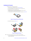
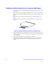
1. Set the heat sink over the processor, lining up the four captive screws with the four
posts surrounding the processor.
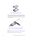
2. Loosely screw in the captive screws on the heat sink corners in a diagonal manner.
Do no fully tighten one screw before tightening another.
3. Gradually and equally tighten each captive screw until each is firmly tightened.
Figure 28. Installing the Heat Sink
TP02076
A
B
TP02328
2
3
1
4