


•
•
•
•
•
•
•
•
•
•
•
•
•
•
•
•
•
•
•
•
•
•
•
•
•
•
•
•
•
•
•
•
•
•
•
•
•
•
•
•
•
•
•
•
•
•
•
•
•
•
•
•
•
•
•
•
•
•
FPC Installation Instructions
13
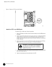
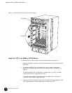
Replace an FPC in an M40 Router
4. Take the FPC offline by pressing and holding its offline button for 5 seconds or until the
green OK LED next to the button goes out. The offline button for each FPC is located on
the craft interface just below the FPC slot.
5. Disconnect the cables from the PICs on the FPC. If a PIC uses fiber-optic cable,
immediately cover each transceiver and the end of each cable with a rubber safety cap.
Arrange the disconnected cables in the cable management system at the top of the
chassis front, to prevent the cables from developing stress points.
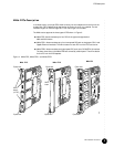
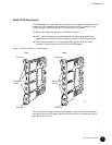
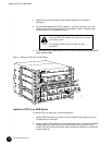
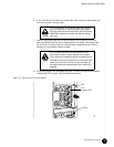
6. Unscrew the thumbscrews at the top and bottom of the FPC.
7. Pull the ends of the extractor clips, which are adjacent to the thumbscrews, away from
the face of the FPC. See Figure 9.
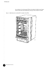
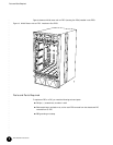
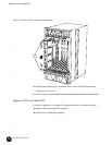
8. Grasp the FPC with both hands and slide it about halfway out of the chassis.
9. Place one hand underneath the FPC to support it, and slide it completely out of the
chassis. Set the FPC on the antistatic foam mat prepared in Step 1, component-side
down and with the PIC faceplates facing you.
10. If you are removing or replacing PICs on the FPC, see the instructions in the
M40 Internet Router Hardware Guide.
Do not look directly into the ends of fiber-optic cables or
into the transceivers on the PIC faceplate. Single-mode
fiber-optic cable and the PICs that use it (such as ATM and
SONET/SDH interfaces) emit laser light that can damage
your eyes.
Do not leave a transceiver uncovered. The safety cap keeps
the port clean and prevents accidental exposure to laser
light.
Avoid bending fiber-optic cable beyond its minimum bend
radius. An arc smaller than a few inches in diameter can
damage the cable and cause problems that are difficult to
diagnose.
To avoid damaging any components, use extra care when
laying the FPC component-side down on the antistatic
mat, particularly if the mat is not made of foam.
Do not stack the FPC on top of or under any other
component.