Disclaimer
.
Name and Functions of Parts
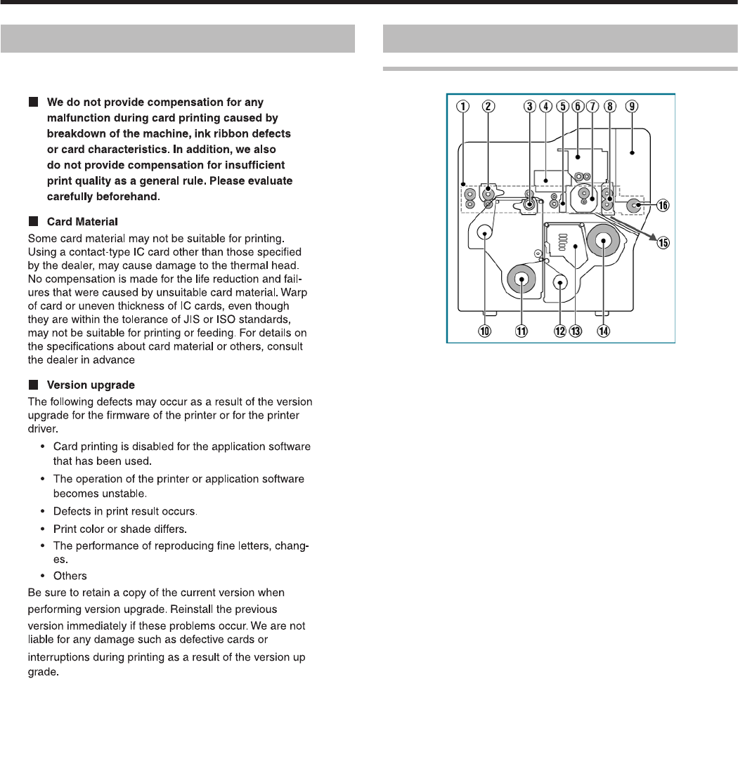
Internal Mechanism Diagram
.
A Card feeder unit
v
This is the roller for feeding cards.
B Bend remedy unit (optional)
v
Corrects bending of the card after retransfer.
C Retransfer heating roller
v
Transfers images printed on the retransfer film to the card.
D Non-contact IC encoder (optional)
v
Writes data to a non-contact IC card.
E Contact section of contact IC encoder (optional)
v
Writes data to a contact IC card.
F Magnetic encoder (optional)
v
Writes data to a magnetic stripe card.
G Card turn over unit (double-sided printer only)
v
Inverts the card.
H Cleaning roller
v
Removes dust or dirt attached to the card.
I Card hopper
v
For loading cards.
J Retransfer film (take-up side)
v
For attaching the take-up side of the retransfer film.
K Retransfer film (supply side)
v
For attaching the unused side of the retransfer film.
L Ink ribbon (take-up side)
v
For attaching the take-up side of the ink ribbon.
M Thermal head
v
Prints images on the retransfer film.
N Ink ribbon (supply side)
v
For attaching the unused side of the ink ribbon.
O NG card outlet
v
Discharges NG cards, such as during card jams.
P Card load roller
v
Roller for loading cards.
Before Use
7


