


DLA-G150HTE
1-16
No.51847
28
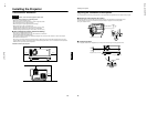
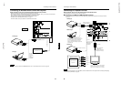
Connecting to Various Devices
Connecting to Computer Devices
Before connection, be sure to turn off both the projector and computer devices.
• Read thoroughly the manual that comes with each device.
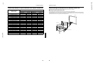
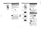
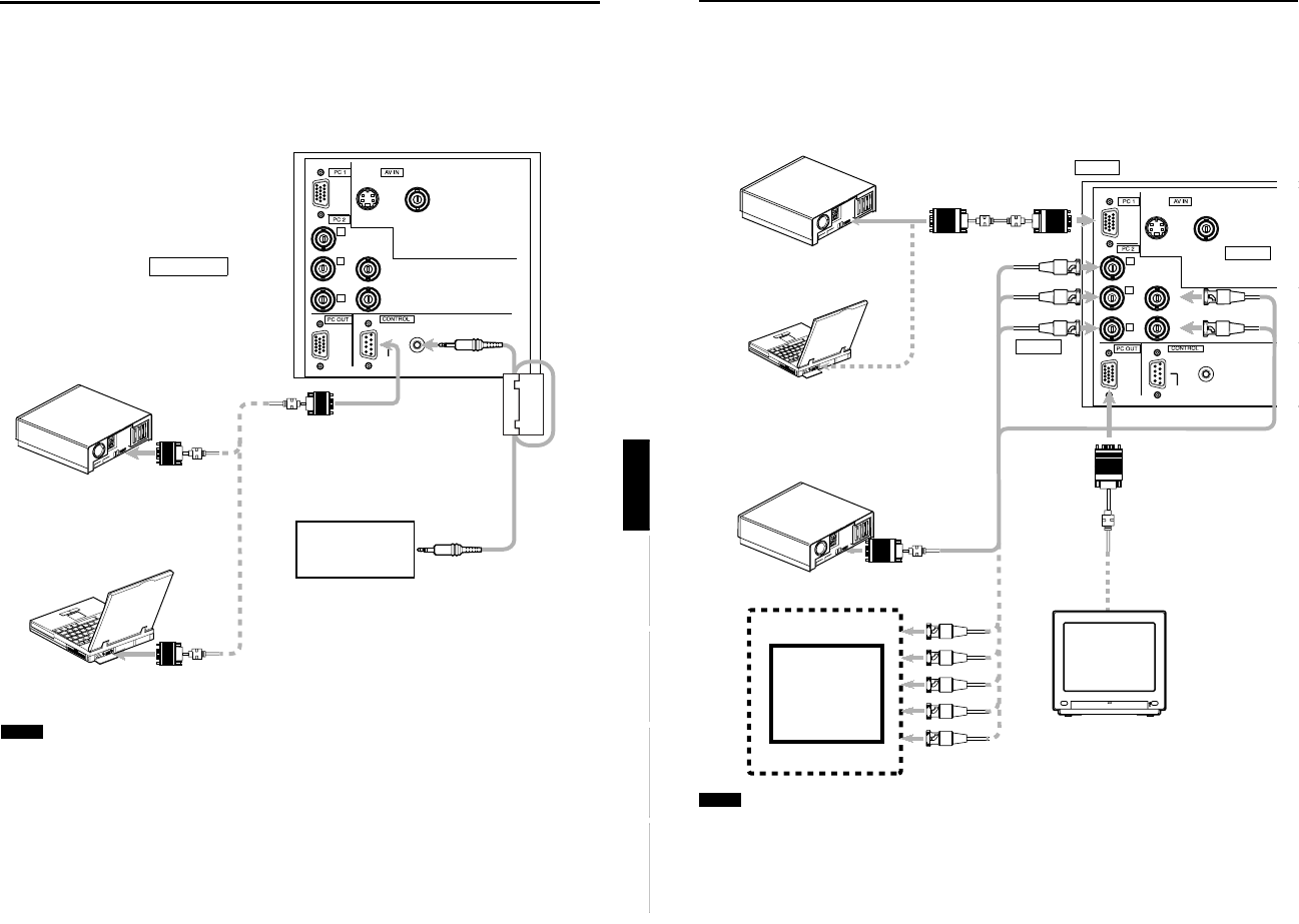
■ Connection to an IBM PC or IBM-compatible computer
• Use the supplied personal computer connection cable. Also, prepare cables required for connecting the devices
connected.
Note
• When the PC2 input terminal is used, “PC2 (BNC)” must be selected from the menu options. Refer to “Setting and Adjusting
Other Functions (OPTIONS)” on page 53.
Y
P
B
/B-Y
P
R
/R-Y
H
V
G
B
R
REMOTE
RS-232C
Y/C VIDEO
POWER
• Desktop type
To PC 1
Personal Computer
connection cable (supplied)
To monitor
connector
To R
To G
To B
• Notebook type
*There are some notebook types which
do not allow the computer’s LCD to work if
an external display is connected. With
such a notebook computer, the LCD
display and external display output need
to be switched.
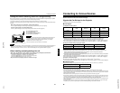
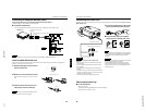
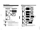
• RGB output devices
• Desktop type
To monitor connector
Separate cable
(separately
available)
To PC 2
To H/Cs
To V
Laser video disc
player, etc.
To G
To B
To R
To H/Cs
To V
To PC 2
To PC 2
To PC 1
To PC OUT
Cable supplied with
the display (or
separately available)
(D-sub 3-row 15-pin)
*When a display monitor is connected to
the PC OUT terminal, you can view the
video from the computer on the monitor.
Display monitor
27
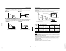
Connecting to Various Devices
ENGLISHDEUTSHFRANÇAISITALIANOESPAÑOL
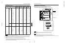
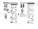
Connecting to Devices which Control the Projector
Before connection, be sure to turn off both the projector and devices to be connected.
• Read thoroughly the manual that comes with each device to be connected.
• By connecting a computer to the RS-232C terminal, you can control the projector. Also, you can make an infrared remote
sensor extension unit and connect it to the REMOTE terminal of the projector.
* Obtain connection cables as required. Use a reverse connection cable.
* For details, refer to “RS-232C external control” on page 71.
* For further details, consult your dealer or an authorized service center.
Note
• When connecting the cable to the REMOTE terminal, refer to “How to attach the ferrite core” on page 29.
Y
P
B
/B-Y
P
R
/R-Y
H
V
G
B
R
REMOTE
RS-232C
Y/C VIDEO
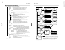
• Desktop type
To RS-232C connector
To RS-232C connector
RS-232C
reverse
connection
cable
(separately
available)
To RS-232C connector
• Note type
To REMOTE terminal
TO CONTROL
Infrared remote sensor
extension unit
(Needs to be made)