


DLA-G150HTE
1-8
No.51847
12
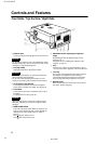
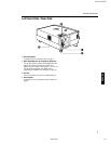
Controls and Features
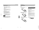
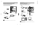
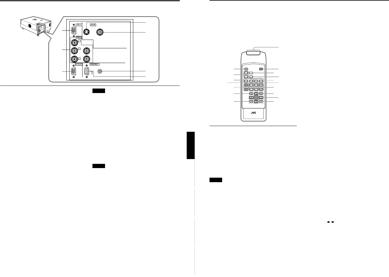
Remote Control Unit
On the remote control, the same buttons as on the control
panel of the projector are provided except for the following
buttons. For the same buttons, operation is the same in
principle.
For remote control only:
DIGITAL ZOOM T/W, QUICK ALIGN., FREEZE, ZOOM T/
W, FOCUS +/–, SCREEN W/S, PC 1, PC 2, VIDEO, Y/C
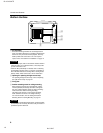
1 Remote control’s signal transmitter
2 OPERATE button
When the projector is in the stand-by mode, press this
button one second or more, and the projector is turned
on, causing the OPERATE indicator to light.
Press it one second or more again, and the projector
goes into the cool-down mode, then stand-by mode.
(Refer to page 31.)
* The OPERATE button will not work for approximately 1
minute from when the light-source lamp is turned on. Use
the button after approximately 1 minute.
Memo
While in the cool-down mode (STAND BY indicator is
blinking):
Even if you press the OPERATE button, the projector is not
turned on. Wait until the projector enters stand-by mode
(STAND BY indicator stays lit).
3 HIDE button
Use this button to turn off the image on the screen
temporarily. Pressing it again makes the image to
resume. (Refer to page 34.)
4 FREEZE button
During projection of an image on the screen, press this
button to obtain a still picture.
To restore normal projection, press it again. (Refer to
page 36.)
* Depending on the video signal source (UXGA, etc.), this
button does not work.
5 VIDEO button
Use this button to select a device such as a video deck
connected to the AV IN terminal (VIDEO or Y/C input
terminal) of the projector. Each time you press the button,
the selection alternates between Y/C and VIDEO. (Refer
to page 32.)
* “Y/C” or “VIDEO” will be displayed on the top right of the
projected image. (This function can be disabled by the
menu.)
6 ZOOM T/W buttons
Use these buttons to adjust the projected screen size.
T (Tele): The projected screen size decreases.
W (Wide):The projected screen size increases.
7 FOCUS +/– buttons
Use these buttons to adjust the focus of the projected
video image.
+ : The focus point becomes more distant.
– : The focus point becomes nearer.
8 MENU button
Use this button to enter or exit the menu mode. The main
menu appears or disappears at the screen. For details,
refer to “Basic Menu Operation” on page 42.
9 Cursor buttons
5
/
∞
/
2
/
3
These buttons are used in the menu mode to select an
item or to set or adjust the value. For details, refer to
“Basic Menu Operation” on page 42.
p ENTER button
This button is used in the menu mode. Use to display the
hierarchical menus. Also use when “ENTER” is displayed
against the item on the menu screen or when the “All
reset” selection is confirmed. For details, refer to “Basic
Menu Operation” on page 42.
q EXIT button
This button is used in the menu mode to return to the
previous menu. When the main menu is displayed, this
button will cause the menu to disappear. For details, refer
to “Basic Menu Operation” on page 42.
w PRESET button
This PRESET button only works as a reset button for the
direct button adjustment of the KEYSTONE button of the
control panel and the DIGITAL ZOOM button of the
remote control. When adjusting the keystone or digital
zoom (when the setting is displayed on the screen) the
adjusted value is reset to that which was set when the
projector was shipped from the factory. Of the menu
items, this button only works for the keystone setting
screen.
e KEYSTONE / buttons
Use these buttons to correct a trapezoidal distortion of
the projected image. (Refer to page 34.)
QUICK
ALIGN.
PC1 PC2
Y/C
VIDEO
HIDE
PRESET
ENTEREXIT
MENU
FREEZE
SCREEN
OPERATE
DIGITAL
ZOOM
ZOOM FOCUS
W
W
S
T
W
T
RM-M150 REMOTE CONTROL UNIT
SCREEN
KEYSTONE
W
S
2
1
3
5
7
8
p
9
4
6
w
q
u
y
e
t
r
11
Controls and Features
ENGLISHDEUTSHFRANÇAISITALIANOESPAÑOL
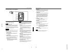
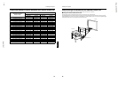
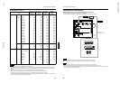
Connector Panel
1 Y/C (S-video) input terminal (Mini DIN 4 pin)
Connect this terminal to the S-video output terminal of a
video deck, etc.
Attach the ferrite core (accessory) to the cable which is
connected to the Y/C input terminal. (Refer to page 29.)
2
VIDEO (composite video) input terminal (BNC)
Connect this terminal to the composite video output
terminal of a video deck, etc.
3 REMOTE terminal (stereo mini jack)
Connect an infrared remote control extension unit, etc. to
this jack.
Attach the ferrite core (accessory) to the cable which is
connected to the REMOTE terminal. (Refer to page 29.)
* For details, consult your dealer.
4 RS-232C CONTROL terminal (D-sub 9 pin)
This is the RS-232C interface-specified terminal. The
projector can be controlled by a computer connected
externally.
* For details, refer to page 27 and 71.
5 PC (computer) OUT terminal (D-sub 3-row 15 pin)
This is the terminal for video output from the monitor of
the computer connected to PC1 or PC2.
The computer input signal projected on the screen is
output. A display monitor can be used by connecting it to
this terminal.
6 PC (computer) 2 input terminals (BNC
×
××
×
5)
These are multipurpose video input terminals that allow
input of the following signals.
• Analog RGB signals, vertical sync (V) signals, and
horizontal sync (H) signals / composite signals (Cs).
(Devices which have analog RGB signal output
terminals can be connected.)
* Input of external sync signals is automatically detected.
Detection of H/V signals or Cs signals causes automatic
switching to external sync. The priority order is H/V > Cs.
• Component signals (Y, B-Y, R-Y) or DTV-format (Y, P
B
,
P
R
) signals. (Devices which have component output
terminals can be connected.)
* For details about DTV-format signals (480i, 480p, 720p,
1080i) compatible with this unit, refer to page 22.
Notes
• In order to use this terminal, the input signal must be used
to select the “PC 2 (BNC)” setting in the option items of the
menu. Use the input signal to change the setting. (Refer to
page 53.)
• When computer-related signals are input, the uppermost
edge of the image may appear to bow if the sync signal
input is composite sync (Cs) or G on sync signal. In this
case, use separate sync signals for vertical sync (V) and
horizontal sync (H).
7 PC (computer) 1 input terminal (D-sub 3-row 15
pin)
This is an input terminal dedicated to computer signals
(RGB video signals and sync signals).
Connect the display output terminal of the computer to
this terminal. When a Macintosh computer is to be
connected, use the supplied conversion adapter for Mac.
Note
• When computer-related signals are input, the uppermost
edge of the image may appear to bow if the sync signal
input is composite sync (Cs) or G on sync signal. In this
case, use separate sync signals for vertical sync (V) and
horizontal sync (H).
5
7
6
2
4
3
1
V
I
D
E
O
P
C
U
P
L
A
M
P
T
E
M
P
S
T
A
N
D
B
Y
M
E
N
U
K
E
Y
S
T
O
N
E
P
R
E
S
E
T
E
X
I
T
E
N
T
E
R
O
P
E
R
A
T
E
H
I
D
E
Y
P
B
/B-Y
P
R
/R-Y
H
V
G
B
R
REMOTE
RS-232C
Y/C VIDEO