


ADDENDUM: Ethernet Cross Cable Wiring Connection
P/N: 2900 - 9999993 A1
This addendum describes the correct wiring for crossover cable connections
and replaces the opening paragraph in the "Connecting the ETHERNET Port
directly to a PC (Crossover Cable)" section in the User Manual as follows:
Connecting the ETHERNET Port directly to a PC (Crossover Cable)
You can connect the Ethernet port of the machine to the Ethernet port on your
PC, via a crossover cable with RJ-45 connectors.
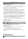
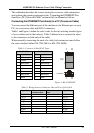
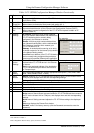
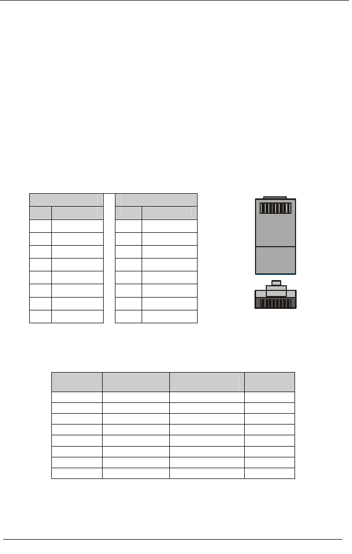
Table 1 and Figure 1 define the color codes for the two existing standard types
of cross cables used in the industry. Table 2 defines how to connect the wires
to the connectors on both ends of the cable.
When manually connecting the ends of a cable, both connectors must follow
the same standard (either EIA /TIA 568A or EIA /TIA 568B).
Table 1: Crossover Cable RJ-45 Types
EIA /TIA 568B
EIA /TIA 568A
PIN Wire Color
PIN Wire Color
1 White-orange
1 White-green
2 Orange
2 Green
3 White-green
3 White-orange
4 Blue
4 Blue
5 White-blue
5 White-blue
6 Green
6 Orange
7 White-brown
7 White-brown
8 Brown
8 Brown
1 8
TOP
FRONT
1 8
Figure 1: RJ-45 PINOUT
Table 2: Wiring between Connector One and Two of the Cable
Signal Pairs PINs on
Connector One
PINs on Connector
Two
Signal Pairs
TX_D1+ 1 3 RX_D2+
TX_D1- 2 6 RX_D2-
RX_D2+ 3 1 TX_D1+
RX_D2- 6 2 TX_D1-
BI_D3+ 4 7 BI_D4+
BI_D3- 5 8 BI_D4-
BI_D4+ 7 4 BI_D3+
BI_D4- 8 5 BI_D3-