


Serial Interface (Option)
B-8
SG - Signal Ground - (Pin 7)
All signals can transmit between the printer and the host computer to send
each signal with a signal ground.
DTR - Data Terminal Ready - (Pin 20)
This output is used as a buffer nearly-full handshake line. It is held high
(above 3 volts) when the buffer can accept more data.
RS-232C Interface Voltage Levels
The voltage levels of the interface signals conform to EIA RS-232C
specifications. SPACE is from 3 volts to 15 volts. MARK is from -3 volts to
-15 volts. Voltages between -3 volts and 3 volts are undefined.
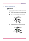
B.3.2 RS-422A Interface
The serial interface is set to the RS-232C mode as the factory default.
However, by changing the jumper connector on the IB-10E interface board,
the interface can be changed to the RS-422A mode.
In the RS-232C mode, the printer can be connected to a personal
computer (or similar device) equipped with an RS-232C serial interface.
(The serial interface is set to the RS-232C mode as the factory default.)
In the RS-422A mode, the printer can be connected to a personal
computer (or similar device) equipped with an RS-422A serial interface.
Changing of the jumper connector should be carried out only by a
Kyocera Mita authorized dealer or Kyocera Mita certified technician.
Kyocera Mita shall not be liable for damage due to improper changing of
the jumper connector.
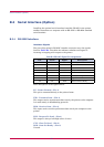
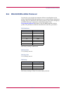
Interface Signals
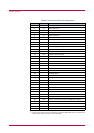
The pins in the printer’s RS-422A interface connector carry the signals
listed in Table B.4.
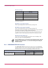
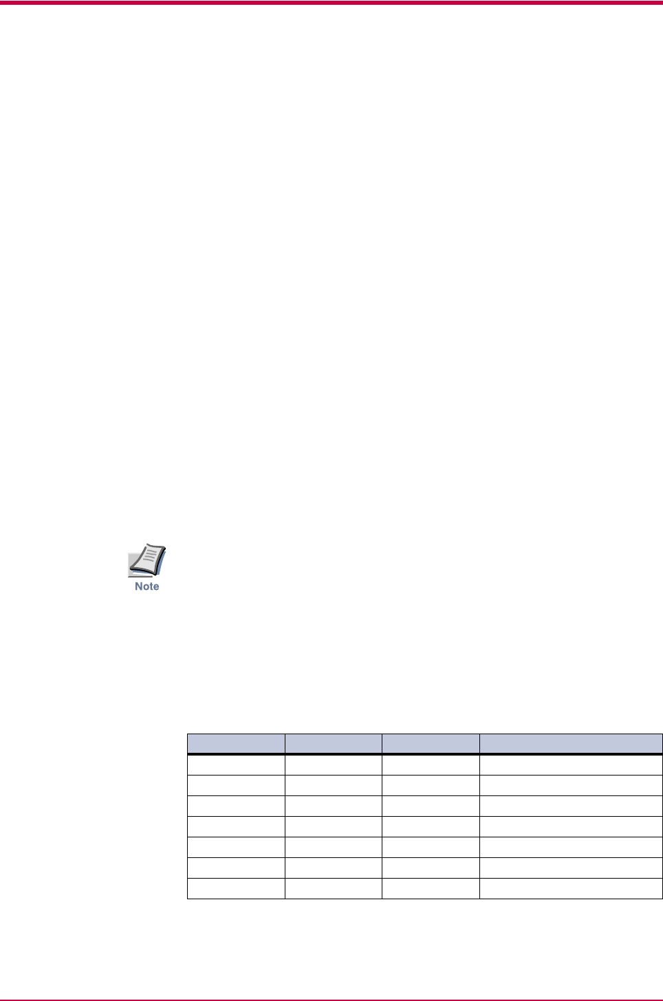
Table B.4 RS-422A Signal Pin Assignments
Pin In/out Signal Description
1 - FG Frame ground
3 In RDA Receive data Inverted
7 - SG Signal ground
9 Out SDA Send data Inverted
10 Out SDB Send data
11 - - +5V DC
18 In RDB Receive data