


Pinouts
J - 6
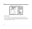
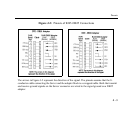
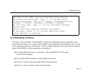
The arrows in Figure J-4 represent the direction of the signal. The pinouts assume that the 8-
conductor cable connecting the Server and the adapter block is a swapped cable. Both the transmit
and receive ground signals on the Server connector are wired to the signal ground on a DB9
adapter.
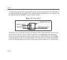
The information about crimping the RJ45 ground wires on page J-4 applies to the DB9 connector
as well.