4: Installation of EDS4100
EDS User Guide 33
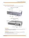
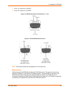
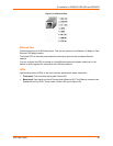
Terminal Block Connector
The back of the EDS4100 has a socket for a terminal block screw connector (not included) for
attaching to an appropriate power source, such as those used in automation and manufacturing
industries. The terminal block connector supports a power range from 42 VDC to 56 VDC. It can
be used with the EDS4100's barrel power connector and PoE capabilities as a redundant power
source to the unit. Vendors who do supply this connector can be found by doing a web search for
part 'Phoenix 1803581 MC 1,5/ 3-ST-3,81'.
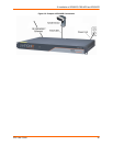
Figure 4-5 Terminal Block Connector Pin Assignments
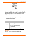
LEDs
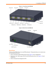
Light-emitting diodes (LEDs) on the front and back panels show status information.
Back panel - Each serial port has a Transmit and a Receive LED. The Ethernet connector has
Speed and Activity LEDs. In addition, the back panel has a Power LED and a Status LED.
Front panel - The front panel has a green Power LED.
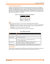
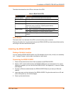
The table below describes the LEDs on the back of the EDS4100.
Table 4-6 Back Panel LEDs
Reset Button
The reset button is on the back of the EDS4100, to the left of the power connector. Pressing this
button reboots the EDS4100 and terminates all serial and Ethernet port data activity.
Pin Signal
Top V+
Middle V-
Bottom Ground
LED Description
Transmit (green) Blinking = EDS is transmitting data on the serial port.
Receive (yellow) Blinking = EDS is receiving data on the serial port.
Power (green) On = EDS receiving power.
Status (yellow) Fast blink = initial startup (loading OS).
Slow blink (once per second) = operating system startup.
On = unit has finished booting.
Speed (yellow) On = EDS is connected to a 100 Mbps Fast Ethernet network.
Off = EDS is connected to a 10 Mbps Ethernet network
Activity (green) Blink = EDS sending data to or receiving data from the Ethernet network.


