


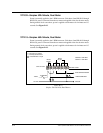

TYPE 14—Electronic Coded Clocks
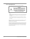
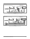
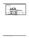
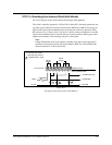
Clocks normally run with 120Vac power. For bells or clock correction, the generator
prestart relay (K6) first turns on for the signal generator to reach frequency. K6 turns on
at the 00 second after a programmed time or manual bell time. Then relay K5 turns on for
three seconds, from the 10th to the 13th second, to apply the generator signal (coded cup
start signal) onto the 120Vac. Bell circuits then turn on for three seconds, in the order
listed below, applying the generator signal onto the 120Vac for decoding by the coded
cups.
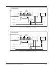
The bell relay contacts must connect in parallel with the normally open contacts of relay
K5. If it is not time for a clock correction signal, K6 turns off at the 59th second. At the
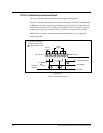
57th minute of each hour, K5 turns on from 57:54 to 58:02, applying the 8-second hourly
correction generator signal onto the 120Vac. At 5:57 AM and 5:57 PM (12-hr correction),
K5 turns on from 5:57:54 to 5:57:08, applying a 14-second 12-hour correction generator
signal onto the 120Vac. For daylight saving, the clocks advance to the proper time by
normal 12-hour correction, not at 2:00 AM. See Figure B-16 on page B-19.
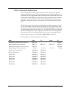
The time sequence of each relay operation is listed below.
Relay From To From To
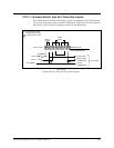
K6 Generator Prestart (hourly correction) HH:57:00 H:59:00
K5 Start Signal (hourly correction) HH:57:00 HH:57:13 HH:57:54 HH:58:02
K6 Generator Prestart (12-hour correction) HH:57:00 HH:59:00
K5 Start Signal (12-hour correction) 5:57:10 5:57:13 5:57:54 5:58:08
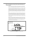
K6 Generator Prestart (bells) HH:MM:00 HH:MM:59
K5 Start Signal (bells) HH:MM:10 HH:MM:13
Bell Circuit 6 HH:MM:20 HH:MM:23
Bell Circuit 5 HH:MM:25 HH:MM:28
Bell Circuit 4 HH:MM:30 HH:MM:33
Bell Circuit 3 HH:MM:35 HH:MM:38
Bell Circuit 2 HH:MM:40 HH:MM:43
Bell Circuit 1 HH:MM:45 HH:MM:48
B-18
24A715/24A715M Master Clock Installation Manual