


Wiring Diagrams List
This appendix contains wiring information and diagrams for the installation of the Dukane 24A715/M Master Clock:
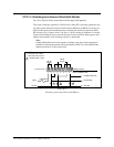
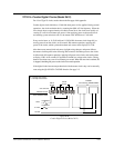
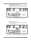
C-1 Wiring the 24A715/M for 120Vac Operation. . . . . . . . . . . . . . . . . . . . . . . . . . . . . . . . . . . . . . . . . . . C-2
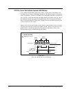
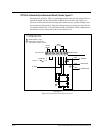
C-2 Wiring the 24A715/M for 220/240Vac Operation . . . . . . . . . . . . . . . . . . . . . . . . . . . . . . . . . . . . . . . C-2
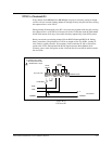
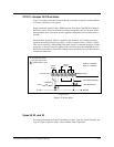
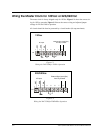
C-3 Typical Signal Device Wiring—Terminal Block P1 . . . . . . . . . . . . . . . . . . . . . . . . . . . . . . . . . . . . . C-3
C-4 Typical Signal Device Wiring—Terminal Block P2 . . . . . . . . . . . . . . . . . . . . . . . . . . . . . . . . . . . . . C-3
C-5 Typical Signal Device Wiring—Terminal Block P3 . . . . . . . . . . . . . . . . . . . . . . . . . . . . . . . . . . . . . C-3
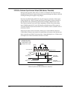
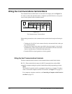
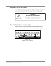
C-6 The Communications Terminal Block . . . . . . . . . . . . . . . . . . . . . . . . . . . . . . . . . . . . . . . . . . . . . . . . C-4
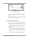
C-7 RS-232 Cable for Permanent Connection to the Communications Terminal Block . . . . . . . . . . . . . C-5
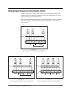
C-8 Synchronizing RS-485 Time Synchronization Devices Without a Buffer . . . . . . . . . . . . . . . . . . . . . C-6
C-9 Using the Master Clock as a Slave to Allow 30 Extra RS-485 Time Synchronizing Devices. . . . . . C-6
C-10 Example of Cable Strain Relief . . . . . . . . . . . . . . . . . . . . . . . . . . . . . . . . . . . . . . . . . . . . . . . . . . . . . C-7
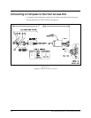
C-11 Computer Cable for Front Access Port. . . . . . . . . . . . . . . . . . . . . . . . . . . . . . . . . . . . . . . . . . . . . . . . C-8
24A715/24A715M Master Clock Installation Manual
C-1
C
Appendix
Wiring Diagrams