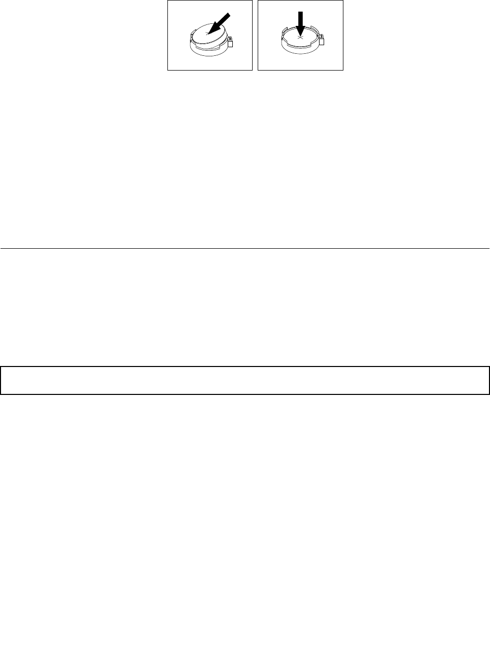
6. Install a new system board battery.
Figure 120. Installing the system board battery
7. If you have lifted up the riser card assembly 1, reinstall it into the chassis. See “Replacing the riser
card assembly 1” on page 136.
8. Dispose of the old system board battery as required by local ordinances or regulations.
What to do next:
• To work with another piece of hardware, go to the appropriate section.
• To complete the replacement, go to “Completing the parts replacement” on page 153
. After you replace
the system board battery, you must reset passwords, reset system date and time, and recongure the
server. See Chapter 5 “Conguring the server” on page 53.
Completing the parts replacement
This topic provides instructions to help you complete the parts replacement and turn on your server.
To complete the parts replacement, you must properly route the cables inside the server, reinstall the server
cover, reconnect all the external cables and, for some devices, update the rmware and run the Setup Utility
program to do further setup.
Reinstalling the server cover and reconnecting cables
Attention: Do not open your server or attempt any repair before reading and understanding “Safety information”
on page iii and “Guidelines” on page 69.
This topic provides instructions on how to reinstall the server cover and reconnect cables to your server.
Attention: For proper cooling and airow, reinstall the server cover before turning on the server. Operating
the server for extended periods of time (more than 30 minutes) with the server cover removed might
damage server components.
Before you begin, print all the related instructions or ensure that you can view the PDF version on another
computer for reference.
Note: Depending on the model, your server might look slightly different from the illustrations in this topic.
To reinstall the server cover and reconnect cables to your server, do the following:
1. Ensure that all components have been reassembled correctly and that no tools or loose screws are
left inside your server.
Chapter 6. Installing, removing, or replacing hardware 153


