


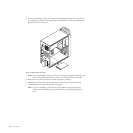
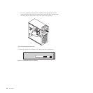
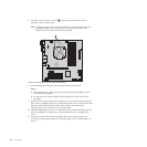
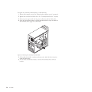
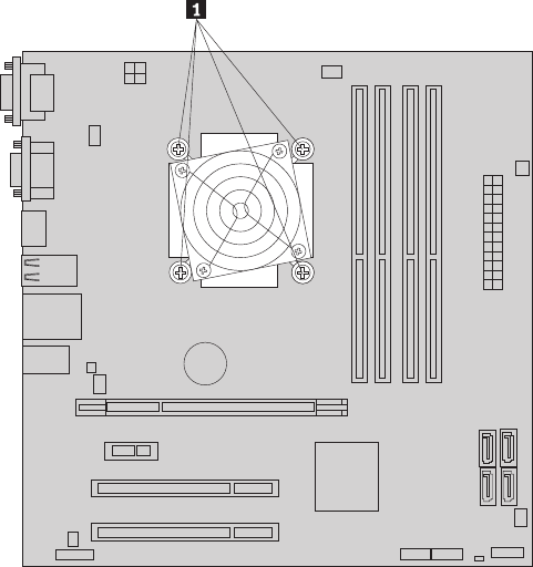
5. Carefully remove the four screws 1 that secure the heat sink and fan
assembly to the system board.
Note: Carefully remove the four screws from the system board to avoid any
possible damage to the system board. The four screws cannot be
removed from the heat sink and fan assembly.
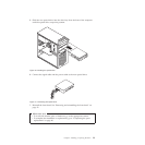
6. Lift the failing heat sink and fan assembly off the system board.
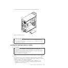
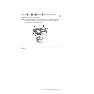
Notes:
a. You might have to gently twist the heat sink and fan assembly to free it
from the microprocessor.
b. Do not touch the thermal grease while handling the heat sink and fan
assembly.
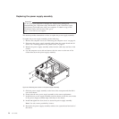
7. Position the new heat sink and fan assembly on the system board so that the
four screws are aligned with the corresponding holes in the system board and
the heat sink and fan assembly cable can be easily connected to the
microprocessor fan connector on the system board.
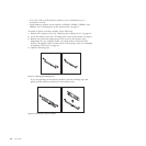
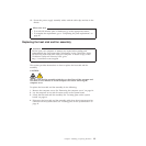
8. Alternate tightening each screw a small and equal amount until the heat sink
and fan assembly is secured to the system board. Do not over-tighten the
screws.
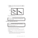
9. Connect the heat sink and fan assembly cable to the microprocessor fan
connector on the system board. See “Locating parts on the system board” on
page 11.
Figure 19. Removing the heat sink and fan assembly
26 User Guide