


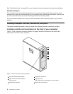
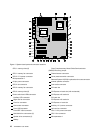

Figure 5 “System board part and connector locations” on page 11 shows the locations of the parts and
connectors on the other type of system board.
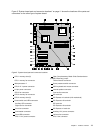
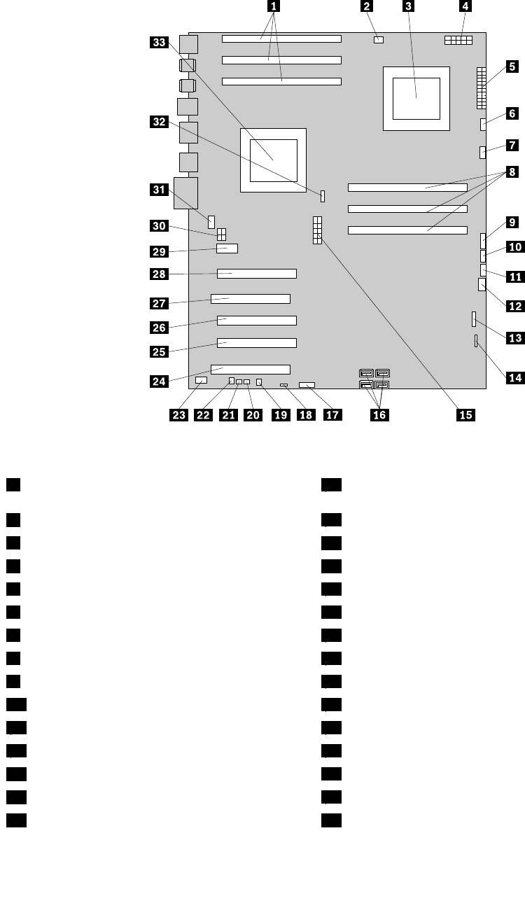
Figure 5. System board part and connector locations
1 CPU 1 memory slots (3) 18 Clear Complementary Metal Oxide Semiconductor
(CMOS) /Recovery jumper
2 CPU 1 memory fan connector
19 Thermal sensor connector
3 Microprocessor 2
20 Cover presence switch connector
4 CPU 2 12 V power connector 21 PS/2 keyboard and mouse connector
5 24-pin power connector 22 Internal speaker connector
6 CPU 2 fan connector
23 Front audio connector
7 CPU 2 memory fan connector 24 PCI card slot
8 CPU 2 memory slots (3) 25 PCI Express x4 card slot (x16 mechanical)
9 Power switch and LEDs connector
26 PCI Express x16 card slot
10 Auxiliary LED connector
27 PCI card slot
11 Right rear fan connector
28 PCI Express x16 card slot
12 Front fan connector
29 PCI Express x1 card slot
13 Card reader connector
30 Auxiliary 12 V power connector
14 Front USB connector
31 Left rear fan connector
15 CPU 1 12 V power connector 32 CPU 1 fan connector
Chapter 1. Product overview 11