


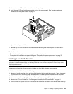
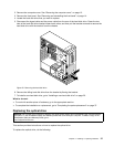
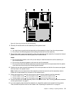
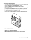
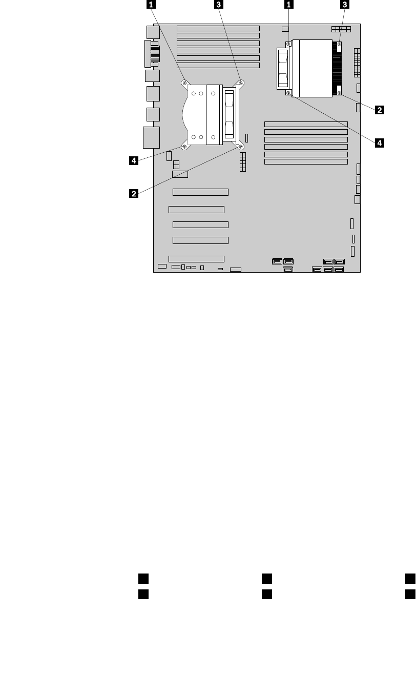
Figure 28. Removing the heat sink and fan assembly
8. Carefully lift the heat sink and fan assembly off the system board.
Notes:
a. You might have to gently twist the heat sink and fan assembly to free it from the microprocessor.
b. Do not touch the thermal grease while handling the heat sink and fan assembly.
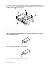
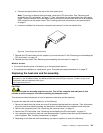
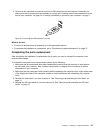
9. Remove the plastic cover from the bottom of the new heat sink and fan assembly to expose the thermal
grease (this cover protects the thermal grease from contamination).
Notes:
a. Do not remove the plastic cover until you are ready to install the heat sink and fan assembly on
the microprocessor.
b. Do not touch the thermal grease on the heat sink and fan assembly.
c. Do not put the heat sink and fan assembly anywhere except on the microprocessor after the plastic
cover has been removed and the thermal grease exposed.
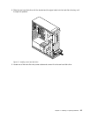
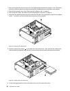
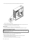
10. Position the new heat sink and fan assembly on the microprocessor so that the four screws are aligned
with the holes in the system board.
Note: Position the new heat sink and fan assembly so that the heat sink and fan assembly cable is
toward the microprocessor fan connector on the system board.
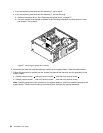
11. Follow this sequence to install the four screws to secure the new heat sink and fan assembly:
a. Partially tighten screw 1 , then fully tighten screw 2 , and then fully tighten screw 1 .
b. Partially tighten screw 3 , then fully tighten screw 4 , and then fully tighten screw 3 .
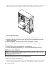
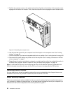
12. Connect the heat sink and fan assembly cable to the system board. See “Locating parts and connectors
on the system board” on page 9.
13. If you are replacing heat sink and fan assembly 2, reinstall the optical drive bracket into the chassis.
Then, reinstall the optical drive into the chassis. See “Replacing the optical drive” on page 27
.
Chapter 2. Installing or replacing hardware 31