


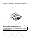
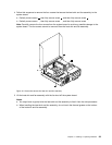
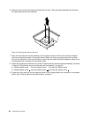
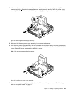
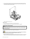

6. Remove the two screws that secure the heat sink fan duct. Then remove the heat sink fan duct from
the failing heat sink and fan assembly.
Figure 19. Removing the heat sink fan duct
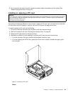
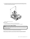
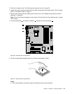
7. Place the new heat sink and fan assembly on the system board so that the four screws are aligned
with the corresponding holes in the system board. Make sure that you properly place the new heat
sink and fan assembly so that you can easily connect the new heat sink and fan assembly cable to the
microprocessor fan connector on the system board.
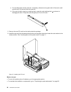
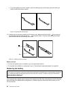
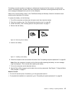
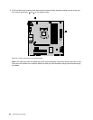
8. Follow this sequence to install the four screws to secure the new heat sink and fan assembly, as shown
in Figure 18 “Screws that secure the heat sink and fan assembly” on page 39:
a. Partially tighten screw 1 , then fully tighten screw 2 , and then fully tighten screw 1 .
b. Partially tighten screw 3 , then fully tighten screw 4 , and then fully tighten screw 3 .
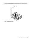
9. Connect the new heat sink and fan assembly cable to the microprocessor fan connector on the system
board. See “Locating parts on the system board” on page 11
.
40 ThinkCentre User Guide