


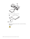
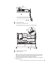
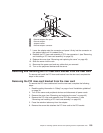
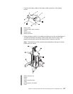
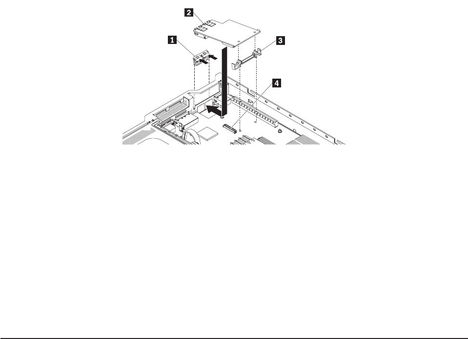
1 Ethernet adapter filler panel
2 Ethernet adapter
3 Adapter bracket
4 Ethernet adapter connector
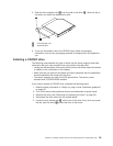
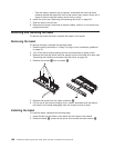
7. Lower the adapter onto the connector and press it firmly into the connector on
the system board until it is seated firmly.
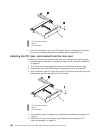
8. Reinstall the PCI riser-card assembly in PCI riser connector 1 (see “Removing
and installing a PCI riser-card assembly” on page 53).
9. Replace the cover (see “Removing and replacing the cover” on page 43).
10. Slide the server into the rack.
11. Reconnect the power cord and any cables that you removed.
12. Turn on the peripheral devices and the server.
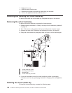
Removing and installing the PCI riser-card bracket from the riser card
To remove and install the PCI riser-card bracket from the riser card, complete the
steps in this section.
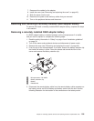
Removing the PCI riser-card bracket from the riser card
To remove the PCI riser-card bracket from the riser-card, complete the following
steps:
1. Read the safety information in “Safety” on page vii and “Installation guidelines”
on page 39.
2. Turn off the server and peripheral devices and disconnect all power cords.
3. Remove the cover (see “Removing and replacing the cover” on page 43).
4. Remove the PCI riser-card assembly from PCI riser connector 1 (see
“Removing and installing a PCI riser-card assembly” on page 53).
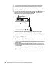
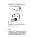
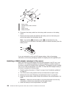
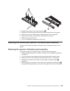
5. Press the retention tabs away from the adapter.
6. Remove the screw that attaches the PCI riser card to the PCI bracket.
Chapter 5. Installing optional devices and replacing customer replaceable units 103