


Installation and Configuration
11
5.0 INSTALLATION AND CONFIGURATION
Do NOT attempt to start the UPS, turn on any circuit breaker or energize the input power until
instructed to do so in 6.0 - Initial Start-Up and Electrical Checks.
Visually inspect the UPS for freight damage. Report any damage to the carrier and your local dealer
or Liebert representative.
Install the UPS indoors in a controlled environment, where it cannot be accidentally turned off. Place
it where air flows unrestricted around the unit. The installation location must be free of water, flam-
mable liquids, gases, corrosives and conductive contaminants. Maintain a minimum clearance of
4 inches (100mm) in the front and rear of the UPS. Maintain an ambient temperature range of
32-104°F (0 to 40°C).
5.1 Install the Main Cabinet
The GXT2-6000RTL630 may be installed in either a tower configuration or in a rack, depending on
available space and use considerations. Determine the type of installation and follow the appropriate
instructions in either 5.1.1 - Tower UPS Installation or 5.1.2 - Rack-Mount UPS Installation.
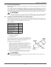
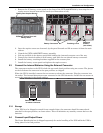
5.1.1 Tower UPS Installation
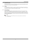
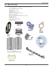
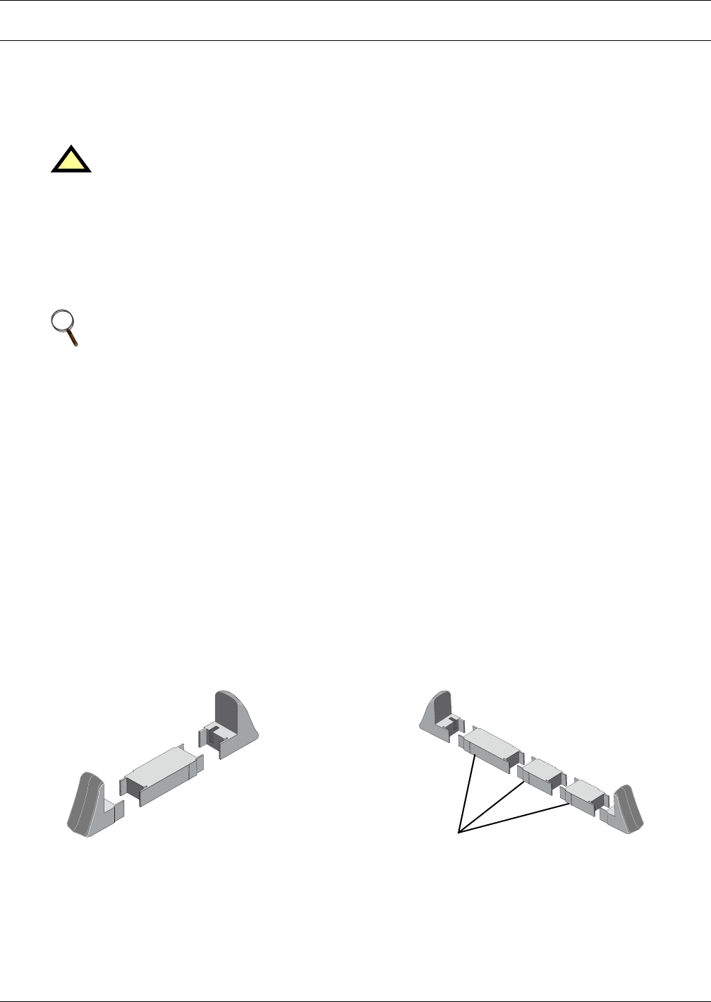
When using the GXT2-6000RTL630 in a tower configuration, use the included support base (shown
below, left) to stabilize the UPS. If any external battery cabinets are added, they will include spacers
to accommodate the additional cabinets (shown below, right).
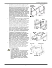
Attach Bezels to Top
When used as a tower, the GXT2-6000RTL630 requires bezels attached to the top. To connect the
bezels:
1. Position the UPS so that the battery compartments are on the right side.
2. Attach the top bezels by placing them on the mounting holes and sliding them toward the rear of
the UPS.
Figure 5 Tower-use support bases, spacers for external battery cabinets
!
CAUTION
The UPS is heavy (see 13.0 - Specifications). Take proper precautions
when lifting or moving it.
NOTE
UPS operation in sustained temperatures above 77°F (25°C) reduces battery life.
3U
2U
2U
5U support base for GXT2
End bases and 3U spacer
3U
2U
2U
Spacers added to support base
to accommodate additional battery cabinets
3U