Maintenance
29
11.2 AC Power Connections
Power connections may be disconnected from the UPS cabinet via a removable distribution box. This
may be a convenient feature if the UPS must be moved a short distance or replaced. This box allows
power connections to be conveniently disconnection from the main UPS cabinet. A label is attached to
the UPS to describe these procedures.
11.2.1 Disconnect
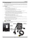
1. DO NOT turn off the branch circuit breaker feeding power the box unless you intend to disconnect
all power to the load.
2. Ensure that the Maintenance Bypass Lamp is ON.
3. Switch to the maintenance bypass position.
The load is now unprotected from line disturbances or interruptions.
4. Turn off the UPS using the front panel controls.
a. If needed, push the OFF button for one second once to transfer the load to bypass.
b. Press the OFF button twice within four seconds to turn the UPS off.
5. Turn off the UPS input circuit breaker on the box at the rear of the UPS.
This input circuit breaker cuts off power only from the connector between the box and UPS. The
input circuit breaker does not cut off power from the manual bypass switch.
6. Turn off the output circuit breaker on the rear of the UPS.
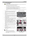
7. Remove the distribution box from the UPS
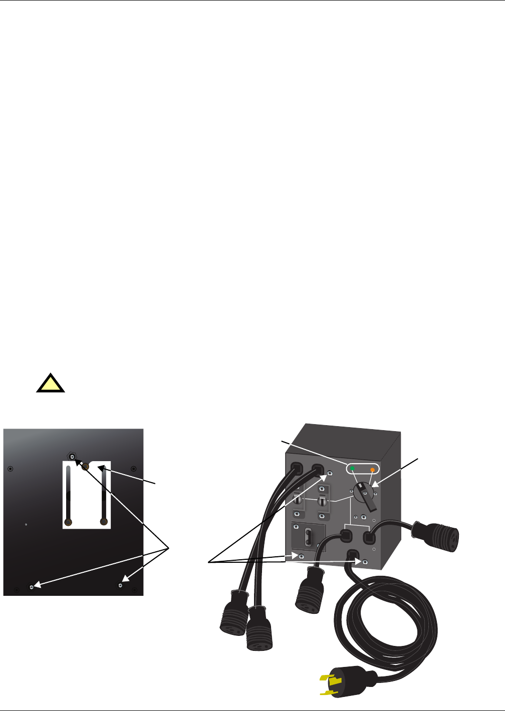
a. Loosen all three captive screws until the box releases.
b. Pull box away from the UPS and set the box aside on a padded surface.
8. Loosen the cover over the electrical connections by backing out the three screws one turn each.
9. Slide the cover over the electrical connections.
10. Gently retighten the three screws loosened in Step 8.
Whenever the power distribution box is not attached to the UPS, the cover must be slid over the
electrical connections to prevent damage or injury.
Figure 8 Power distribution box, PD-L630
!
CAUTION
Power is still passing through the power distribution box from the utility supply to the load.
OUTPUT
BREAKER
20A 240V
~/T
OUTPUT
BREAKER
20A 240V~/T
O
N
O
N
IN
PP
U
T
OUTPUT ONLY C B DO
ES
N
OT
CO
N
N
ECT BY
PAS S POW
E
R TO
M
ANUAL B
YPASS SW
ITC
H.
BREAKER 30A
O
N
O
FF
O
FF
O
FF
U
PS
U
TILITY
M
AIT
ANENCE BYPASS
AVAILABLE
U
PS
AVAILABLE
CONNECTOR PROTECTIVE COVER DO NOT REMOVE SCREWS
PRIOR TO INSTALLATION OF BOX ON UPS
-LOOSEN THREE SCREWS 1 TURN
- SLIDE COVER TO EXPOSE CONNECTOR
-TIGHTEN SCREWS GENTLY
UPON REMOVAL OF BOX FROM UPS
-LOOSEN THREE SCREWS 1 TURN
-SLIDE COVER TO REACH END SCREW AND COVER COMMUNICATION
-TIGHTEN SCREWS GENTLY
Maintenance
Bypass Lamps
Maintenance
Bypass Switch
Captive
Screws
(attach
box to
UPS)
Rear View
Front View
Protective
Cover Over
Connectors


