


6 Unpacking and Installation
2.2 Input and Output Power Connections
All wiring should be installed by a qualified electrician. All wiring must comply with NEC and
applicable local codes.
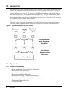
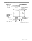
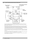
If the unit is not furnished with input power cables, then input power connections are made to
terminal blocks located inside the unit. Refer to the unit outline drawings furnished with the unit
or Figure 2 and Figure 3 for the location of the input power connections. Terminal blocks for
switches rated 13 to 20 amps accept wires sizes of #14 to #10 AWG. Terminal blocks for switches
rated 25 to 60 amps accept wire sizes of #12 to #6 AWG.
!
WARNING
RISK OF ELECTRICAL SHOCK. HAZARDOUS VOLTAGES ARE
PRESENT INSIDE THE SMARTSWITCH. VERIFY THAT THE ALL
INPUT POWER SOURCES ARE DE-ENERGIZED AND LOCKED
OUT BEFORE MAKING CONNECTIONS INSIDE THE UNIT. THE
SMARTSWITCH IS INTENDED TO BE FED FROM TWO
SOURCES. BE SURE ALL SOURCES OF POWER ARE DE-
ENERGIZED AND LOCKED OUT BEFORE MAKING
CONNECTIONS INSIDE THE UNIT.
!
WARNING
RISK OF UNIT DAMAGE. THE SMARTSWITCH IS INTENDED TO
BE OPERATED FROM SOLIDLY GROUNDED POWER SOURCES.
OPERATION FROM OTHER THAN SOLIDLY GROUNDED
POWER SOURCES MAY CAUSE MISOPERATION OR DAMAGE
TO THE UNIT.
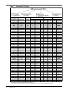
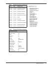
Wire Size
AWG
Tightening Torque
Lb.-in (N-m)
#14 - #10 20 (2.3)
#8 25 (2.9)
#6 35 (4.0)