Unpacking and Installation 9
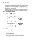
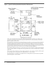
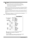
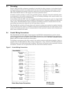
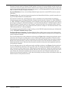
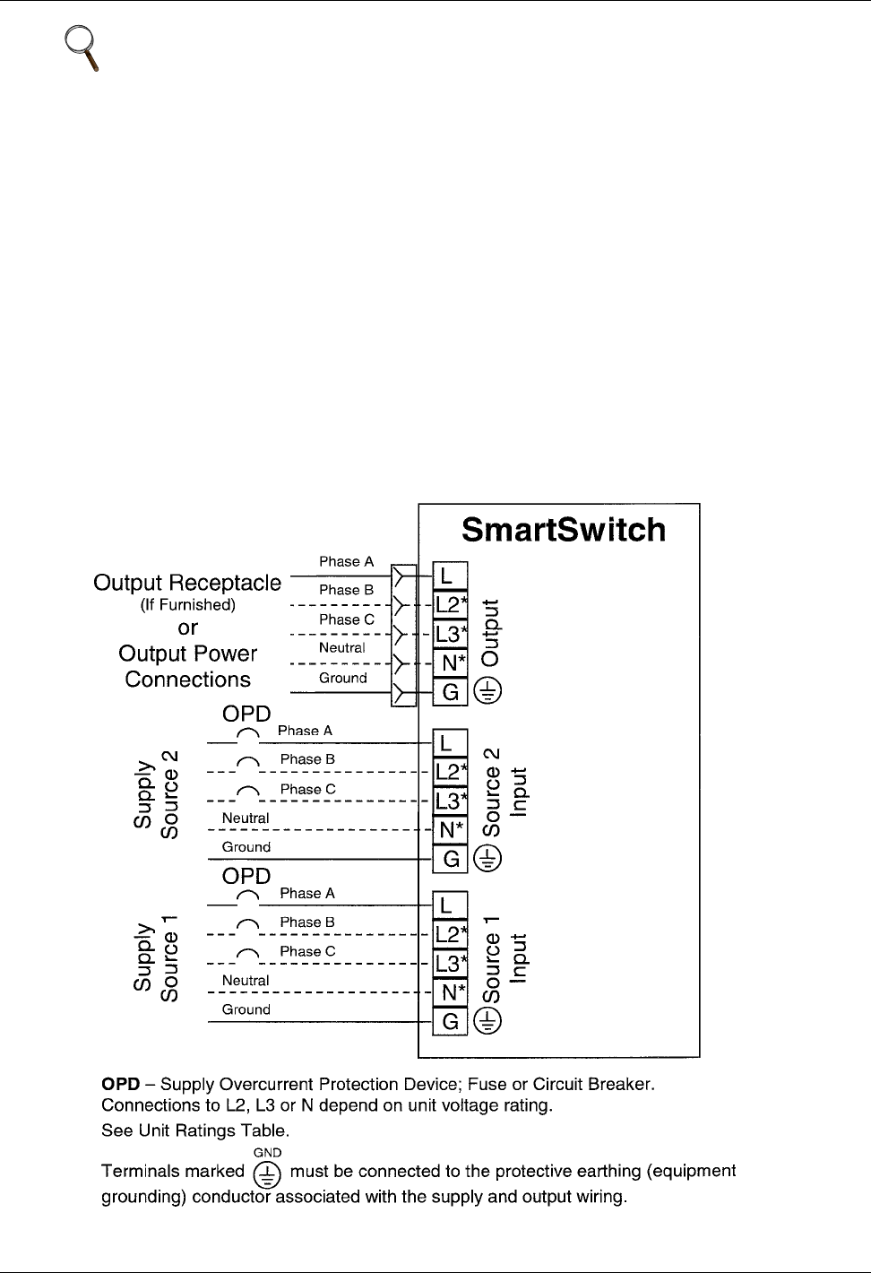
Figure 4 shows the typical input and output power connections to the SmartSwitch. The Smart-
Switch can accept up to 3 phase conductors, a neutral conductor and an equipment grounding con-
ductor per input and output to match the specified supply voltage configuration. See the unit
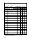
ratings table (Table 1) for the required number of phase and neutral conductors required for the
particular SmartSwitch used.
For example, for a NEMA 520R2 SmartSwitch application, one phase and neutral conductor and
equipment grounding conductor per source are required whereas for a NEMA L1530R1 Smart-
Switch application, three phase conductors and an equipment grounding conductor per source are
required.
The output power connections can be to terminal blocks located inside the SmartSwitch (as shown
in Figure 2, Figure 3, and Figure 4) or to receptacle(s) located on the SmartSwitch.
Figure 4 Typical Input and Output Power Connections
NOTE
The two input sources need to be nominally of the same voltage level,
frequency and phase rotation. To ensure virtually uninterrupted transfers
between the two AC sources, the two input sources must be synchronized,
typically within 5 to 15 electrical degrees. For single phase circuits, be sure
to use the same phase from each input power source to maintain
synchronized inputs to the SmartSwitch.


