


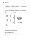

4 Introduction
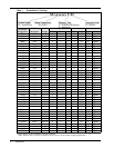
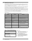
Table 1 SmartSwitch™ Ratings
Connector
Designation
Receptacle Voltage
No. of Conductors OPD* Enclosure
Phase Neutral Gnd Poles Amps Type Refer to
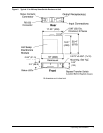
IBMA 3743 208 2 — 1 2 20 R Figure 2
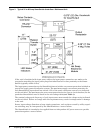
IBMB 3744 208 3 — 1 3 15 U Figure 3
IBMC 3753 208 2 — 1 2 30 U Figure 3
IBMD 3754 208 3 — 1 3 30 U Figure 3
IBME 7324 208 3 — 1 3 60 U Figure 3
420R9V 420R9V 208 3 — 1 3 20 U Figure 3
460R9V 460R9V 208 3 — 1 3 60 U Figure 3
515R2 5262 120 1 1 1 1 15 U Figure 3
515R4 (2) 5262 120 1 1 1 1 15 R Figure 2
520R2 5362 120 1 1 1 1 20 R Figure 2
520R4 (2) 5362 120 1 1 1 1 20 R Figure 2
530R1 9308 120 1 1 1 1 30 U Figure 3
615R2 5662 208 2 — 1 2 15 R Figure 2
620R2 5462 208 2 — 1 2 20 R Figure 2
630R1 9330 208 2 — 1 2 30 U Figure 3
1420R1 8410 120/208 2 1 1 2 20 U Figure 3
1430R1 9430 120/208 2 1 1 2 30 U Figure 3
1520R1 8420 208 3 — 1 3 20 U Figure 3
L515R1 4710 120 1 1 1 1 15 R Figure 2
L520R1 2310 120 1 1 1 1 20 R Figure 2
L530R1 2610 120 1 1 1 1 30 U Figure 3
L615R1 4560 208 2 — 1 2 15 R Figure 2
L620R1 2320 208 2 — 1 2 20 R Figure 2
L630R1 2620 208 2 — 1 2 30 U Figure 3
L1420R1 2410 120/208 2 1 1 2 20 U Figure 3
L1430R1 2710 120/208 2 1 1 2 30 U Figure 3
L1520R1 2420 208 3 — 1 3 20 U Figure 3
L1530R1 2720 208 3 — 1 3 30 U Figure 3
L2120R1 2510 120/208 3 1 1 3 20 U Figure 3
L2130R1 2810 120/208 3 1 1 3 30 U Figure 3
FW120 None 120 1 1 1 1 20 R Figure 2
FW130 None 120 1 1 1 1 30 U Figure 3
FW220 None 208 2 — 1 2 20 R Figure 2
FW230 None 208 2 — 1 2 30 U Figure 3
FW230N None 208/120 2 1 1 2 30 U Figure 3
FW330 None 208 3 — 1 3 30 U Figure 3
FW330N None 208/120 3 1 1 3 30 U Figure 3
FW360 None 208 3 — 1 3 60 U Figure 3
FW113 None 230 1 1 1 1 13 R Figure 2
FW325N None 400/230 3 1 1 3 25 U Figure 3
FW350 None 400 3 — 1 3 50 U Figure 3
Consult Factory for other available connectors not shown.
* OPD - Maximum size of Overcurrent Protection Device (fuse or circuit breaker) supplying SmartSwitch.