


ii
FIGURES
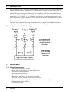
Figure 1 Typical SmartSwitch One-Line Diagram . . . . . . . . . . . . . . . . . . . . . . . . . . . . . . . . . . . . . . . . . . 2
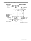
Figure 2 Typical 15 to 20 Amp SmartSwitch Rackmount Unit . . . . . . . . . . . . . . . . . . . . . . . . . . . . . . . . 7
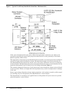
Figure 3 Typical 25 to 60 Amp SmartSwitch Underfloor / Wallmount Unit . . . . . . . . . . . . . . . . . . . . . . 8
Figure 4 Typical Input and Output Power Connections . . . . . . . . . . . . . . . . . . . . . . . . . . . . . . . . . . . . . . 9
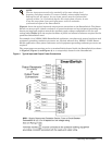
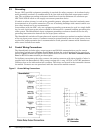
Figure 5 Control Wiring Connections . . . . . . . . . . . . . . . . . . . . . . . . . . . . . . . . . . . . . . . . . . . . . . . . . . . 10
Figure 6 Bypass / Transfer Control Switch . . . . . . . . . . . . . . . . . . . . . . . . . . . . . . . . . . . . . . . . . . . . . . . 14
TABLES
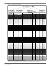
Table 1 SmartSwitch™ Ratings . . . . . . . . . . . . . . . . . . . . . . . . . . . . . . . . . . . . . . . . . . . . . . . . . . . . . . . . 4
Table 2 SmartSwitch Status Indicators . . . . . . . . . . . . . . . . . . . . . . . . . . . . . . . . . . . . . . . . . . . . . . . . . 11
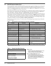
Table 3 RS-232 ASCII Communication Port Customer Commands . . . . . . . . . . . . . . . . . . . . . . . . . . . 12
Table 4 Example View Status Response . . . . . . . . . . . . . . . . . . . . . . . . . . . . . . . . . . . . . . . . . . . . . . . . . 12
Table 5 Example View Event Log Response . . . . . . . . . . . . . . . . . . . . . . . . . . . . . . . . . . . . . . . . . . . . . . 13
Table 6 Example View Settings Response . . . . . . . . . . . . . . . . . . . . . . . . . . . . . . . . . . . . . . . . . . . . . . . 13
Table 7