


16 Operating Guidelines
Transfer Control switch to “Bypass To S2” position. If source 2 is not available and the load is not
connected to source 2 before the switch is rotated to the “Bypass To S2” position, power to the load
may be interrupted. If the load is connected to source 1 and the SmartSwitch will not transfer the
load to source 2, initiate a bypass to source 1.
System Shutdown. Power to both SmartSwitch inputs must be turned OFF to ensure system
shutdown.
Transfer Test. For continued protection against the SmartSwitch failure, periodic transfer test-
ing of the SmartSwitch is recommended.
For manual transfer test, with both input sources available and synchronized (no Summary
Alarm present), rotate the Bypass/Transfer Control switch from the “Normal” to “Man. XFER S1”
or “Man. XFER S2” positions (whichever is the alternate source) and observe proper switch trans-
fers (observe change in “On Preferred Source” and “On Alternate Source” indicator lights). Return
Bypass/Transfer Control switch to the “Normal” position and after the retransfer delay, observe
proper switch transfer back to the preferred source (observe change in “On Alternate Source” and
“On Preferred Source” indicator lights).
For automatic (programmable) transfer testing, see the RS-232 communications port information
in 3.3 - RS-232 Communications Port.
Preferred Source Selection. The SmartSwitch allows either input source to be designated as
the preferred source to which the load is transferred to and remains transferred to as long as the
source remains available.
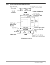
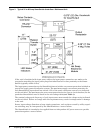
For 13 to 20 amp units in the rackmount enclosure (see Figure 2), to change the preferred source,
place the unit in bypass to either input source, following the bypass procedure. Unlock and the
removable electronics module. Slide out (remove) the electronics module from the main enclosure.
Rotate the Preferred Source selector switch located on the rear of the electronics module to the
desired preferred source. Re-insert the electronics module in the main unit completely and lock
the electronics module.
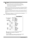
On 25 to 60 amp units in the wall-mount and underfloor enclosure (see Figure 3), the preferred
source is indicated by labeling on the top of the unit. To change the preferred source, place the
unit in bypass to either input source, following the bypass procedure. Unlock and unlatch the two
latches on the removable electronics module. Remove the electronics module from the main enclo-
sure. Rotate the electronics module and re-insert in the main unit. Re-latch and lock the two
latches on the electronics module. Verify that the labeling on the top of the unit indicates that the
desired source is the preferred source.