


10 Unpacking and Installation
2.3 Grounding
Proper, NEC-specified equipment grounding is required for safety purposes. An insulated equip-
ment grounding conductor is recommended to be run with each input and output power connec-
tion. The equipment grounding conductors should be at least the minimum size conductor per
NEC Table 250-95 based on the supply overcurrent protection device.
If conduit or other wireway is used as the grounding means, adequate electrical continuity must
be maintained at all conduit connections. The use of isolating bushings with a metal conduit can
be a safety hazard and is not recommended.
In accordance with the NEC, only one equipment grounding system may be used in a single build-
ing. As such, both input power sources should be referenced to a common building grounding elec-
trode system. The SmartSwitch input equipment grounding conductors should not be the only
grounding interconnection between the two input power sources.
The SmartSwitch switches all input phase and neutral conductors to maintain complete isolation
of the two input power sources. A common neutral-to-ground bond for the two input sources is not
required for proper operation but is recommended to avoid potential common mode disturbances
when source transfers are made.
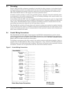
2.4 Control Wiring Connections
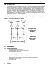
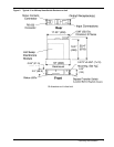
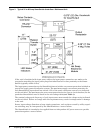
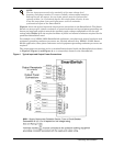
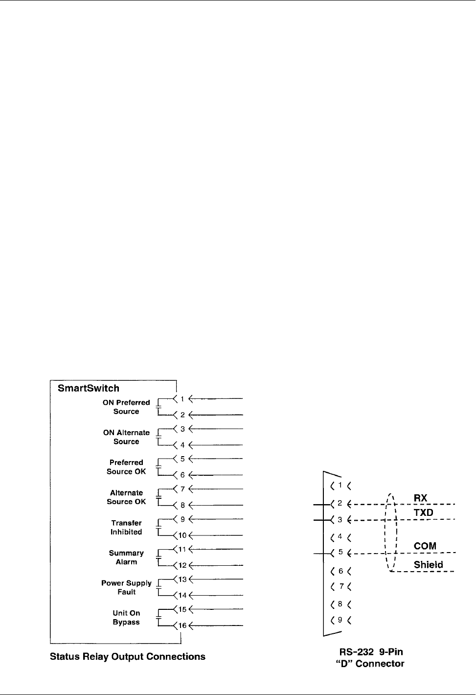
The SmartSwitch includes relay output contacts and RS-232 communications port for remote
indication of switch status. Figure 2 and Figure 3 show the typical locations of the control con-
nectors. Figure 5 shows the typical control connections. Refer to 3.3 - RS-232 Communications
Port for RS-232 communication port description.
To facilitate connection to the relay contacts, the mating connector with short pigtails of wires is
supplied with the SmartSwitch. Relay contact ratings are 1 amp, 125 VAC or 30 VDC maximum.
Contacts close on the indicated switch condition. The relays are located in the removable electron-
ics module. Contacts are not operational with the electronics module removed.
Figure 5 Control Wiring Connections