


EtherFast
®
Cable/DSL Routers
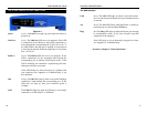
Full/Col Green. The Full/Col LED also serves two purposes. If this
LED remains lit, a LAN port connection is being successful-
ly maintained. If the LED flickers, the connection is experi-
encing collisions. Infrequent collisions are normal.
If this LED flickers too often, there may be a problem with
your connection. See “Appendix A: Troubleshooting” if you
encounter this problem.
10/100 Orange. The 10/100 LED lights up when a successful
100 Mbps connection is made through the corresponding
port.
If a connection is running at 10 Mbps, the 10/100 LED will
not light up.
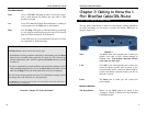
The WAN Indicators
Link Green. The Link LED lights up when a successful connec-
tion is made between the Router and your broadband device
or network.
Act Green. The Act LED flickers when the Router is sending or
receiving data over the WA N port.
Diag Red. The Diag LED lights up when the Router goes through
its self-diagnostic mode. It will turn off upon successful
completion of the diagnosis.
If this LED stays on for an abnormally long period of time,
see “Appendix A: Troubleshooting.”
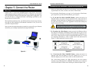
Proceed to “Chapter 5: Connect the Router.”
13
Instant Broadband
™
Series
12
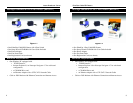
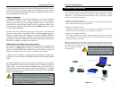
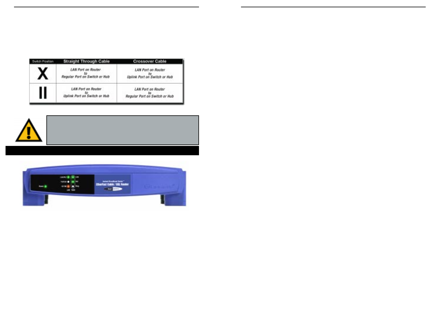
The Crossover Switch
When “uplinking,” or connecting two pieces of network hardware together,
such as a hub and a switch, a general rule of thumb is to plug one end of a
network cable into a straight-through port, and the other end into a crossover
port (uplink port). Standard ports are straight-through ports, and uplink ports
are crossover ports.
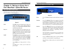
The
1-
Port
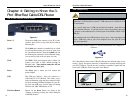
Power Green. The Power LED lights up green when the Router is
powered on.
Link/Act Green. The Link/Act LED serves two purposes. If the LED
is continuously lit, the Router is successfully connected to a
device through the LAN port. If the LED is flickering, the
Router is actively sending or receiving data through the LAN
port.
Important: The chart in Figure 3-2 is for reference purposes
only. Every network is different. If you do not make a connec-
tion to a hub or switch by using the settings above, change the
position of the Crossover Switch.
The 1-Port Router’s Front Panel LEDs
Figure 3-2
Figure 3-3