


C-2 SP Switch Router Adapter Guide - 1.4 Update 2
Network Configuration Examples
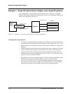
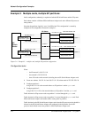
Example 1: Single SP Switch Router Adapter card, single SP partition
In this configuration, a single SP Switch Router Adapter card is connected to a single SP
partition. The IP address of the SP Switch network is 198.174.11. The partition of SP nodes is
shown in the shaded area of Figure C-1.
Figure C-1. Example 1– single card, single SP partition network configuration
Configuration requirements
• All network nodes (SP Switch Router Adapter card and SP processor nodes) must have the
same IP net in the network portion of their IP address. In the example, this is 198.174.11.
• ARP is enabled on the SP Switch network to provide the most flexibility in assigning IP
addresses
• If ARP is disabled on the SP Switch, the Host Offset value must be defined to all network
nodes (SP Switch Router Adapter card and SP processor nodes), and the IP addresses
assigned to the nodes must have host values that are determined by the host offset and
switch port. Please refer to the RS/6000 SP Planning, Volume 2, Control Workstation and
Software Environment manual for details.
If the network is 198.174.11.0 and the netmask is 255.255.255.0, then the IP address of the
SP Switch Router Adapter card and any SP processor nodes must be between
198.174.11.1 and 198.174.11.254. The SP Switch Router Adapter card will not properly
forward IP data to nodes that are assigned with an IP address that is not in this address
range (those IP messages will most likely be forwarded to the default gateway).
SP
SP processor node
SP processor node
SP processor node
net 198.174.11.0
SP Switch Router
Adapter card
mask 255.255.255.0
mask 255.255.255.0
net 198.174.11.0
Partition
Switch
Router
SP Switch