


C-6 SP Switch Router Adapter Guide - 1.4 Update 2
Network Configuration Examples
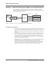
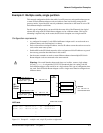
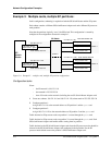
Example 3: Multiple cards, multiple SP partitions:
In this configuration, subnetting is required on both the SP Switch Router and the SP system.
Each subnet contains a different SP Switch Router Adapter card and a different SP processor
node partition.
Note that the partitions logically “cross” the SP Switch. This configuration is created by
multiples of the configuration discussed in example 1.
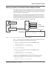
Figure C-4. Example 3 – multiple card, multiple SP partition configuration
Configuration tasks
Given:
– the IP network is 198.174.11.0
– the netmask is 255.255.255.0
– there 254 nodes on the network (including the two SP Switch Router Adapter cards
1 Create two subnets: 198.174.11.0 and 198.174.11.128, subnet mask of 255.255.255.128
2 Configure partition 1:
Assign 198.174.11.0 as the network address to SP partition 1 and the gt010 card
3 Configure partition 2:
Assign 198.174.11.128 as the network address to SP partition 2 and the gt020 card
Traffic destined to SP processor nodes on partition 1 is routed through the gt010 card.
Traffic destined to SP processor nodes on partition 2 is routed through the gt020 card. Each
SP Switch Router Adapter card handles traffic coming from its partition.
Traffic destined to the SP Switch Router Adapter cards from the SP processor nodes should be
directed to the SP Switch Router Adapter card configured in their partition. Set the SP
processor node default route to the partition’s SP Switch Router Adapter card.
SP processor node
SP processor node
SP processor node
net 198.174.11.128
mask 255.255.255.128
mask 255.255.255.128
net 198.174.11.128,
partition 2
SP processor node
SP processor node
SP processor node
net 198.174.11.0
mask 255.255.255.128
mask 255.255.255.128
net 198.174.11.00,
partition 1
SP Switch Router
Adapter card 2 - gt020
SP Switch Router
Adapter card 1 - gt010
SP Switch
partition 1
partition 2
SP
Switch
Router