


Configuring the SP Switch Router Adapter
Configuration required on the SP system
SP Switch Router Adapter Guide - 1.4 Update 2 October 22, 1999 2-15
Multiple frames for multiple system connections
SP Switch Router Adapter cards in an SP Switch Router can connect to different switch boards
in the same SP system. A configuration problem could arise in which the SP Switch Router
Adapter cards would be assigned the same node number if each card plugged into the same
port position on each switch board.
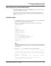
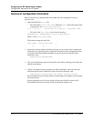
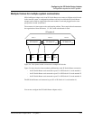
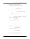
The construct of a frame removes the configuration problem. The example below demonstrates
the organization of three SP frames, 1, 2, and 3 with switch boards in each.
Figure 2-4. How frames enable connections to multiple SP Switches
Figure 2-4 shows how the frame numbering differentiates each SP Switch Router connection:
– the SP Switch Router card connected to port J31 of SP Switch A1 is node number 9
– the SP Switch Router card connected to port J31 of SP Switch A2 is node number 25
– the SP Switch Router card connected to port J31 of SP Switch A3 is node number 41
The SP Switch Router card connected to port J15 of SP Switch A1 is node number 16.
You can now configure the SP Switch Router Adapter card(s).
Frame 1
SP system A
J7
J31
J23
J15
SP Switch A1
J7
J31
J23
J15
SP Switch A2
J7
J31
J23
J15
SP Switch A3
Frame 2 Frame 3
SP Switch Router
gt000
node 9
gt010
node 16
gt020
node 25
gt030
node 41