


C-4 SP Switch Router Adapter Guide - 1.4 Update 2
Network Configuration Examples
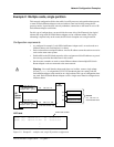
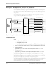
Configuration tasks
Given:
– the IP network is 198.174.11.0
– the netmask is 255.255.255.0
– there can be up to 254 nodes on the network
(including the two SP Switch Router Adapter cards)
1 Configure the SP processor nodes with 198.174.11.0 as the network and 255.255.255.0
as the netmask.
The address of individual nodes must be between 198.174.11.1 and 198.174.11.254.
2 Configure the two SP Switch Router Adapter cards as follows:
- divide the 198.174.11.0 network into two subnets, 198.174.11.0 and 198.174.11.128,
with a subnet netmask of 255.255.255.128
- assign any of the 198.174.11.1-126 addresses, mask 255.255.255.128, to card gt010
- assign any of the 198.174.11.129 -254 addresses, mask 255.255.255.128, to card gt020
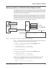
Incoming traffic (going to SP processor nodes)
Traffic destined to node addresses 198.174.11.1 to 198.174.11.127 is routed through gt010.
Traffic destined to node addresses 198.174.11.129 to 198.174.11.255 is routed through gt020.
Each SP Switch Router Adapter card handles roughly half the incoming traffic.
Outgoing traffic (coming from SP processor nodes)
Traffic destined to the SP Switch Router Adapter cards from SP processor nodes is directed by
changing the SP processor nodes’ default route or adding static routes to force their outgoing
traffic to be sent to gt010 or gt020. For example, half of the nodes would have their default
route set to the gt010 card and the other half would have their default route set to the gt020
card.
If more SP Switch Router Adapter cards are configured, you must divide the net into more
(but smaller) subnets. For example, if the number of cards increases to four, you would set the
subnet netmask to 255.255.255.192 (ff.ff.ff.c0).