


Impulse DataLogger Series 3 Instruction Manual 2/1/05
7 of 16
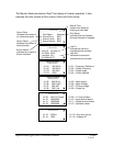
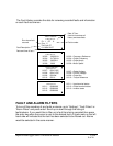
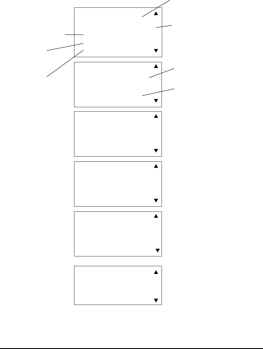
The Monitor Mode provides for Real-Time display of Inverter operation. It also
indicates the total number of Run events, Alarm and Fault events.
- MONITOR MODE -
Run Status: Stopped
Accum Runs: 0001
Accum Faults: 0001
Accum Alarms: 0000
01/28/04 08:44:13
- MONITOR MODE -
Last Flt: DC Bus UV
01/28/04 08:35
Last Alm: UL1
01/29/04 02:37
01/28/04 08:44:13
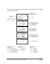
- MONITOR MODE -
U1-01: 000.00 Hz
U1-02: 000.00 Hz
U1-03: 000.00 A
U1-04: 0000
01/28/04 08:44:13
- MONITOR MODE -
U1-05: 000.00 Hz
U1-06: 000.0 VAC
U1-07: 000 VDC
U1-08: 000.0 Hp
01/28/04 08:44:13
- MONITOR MODE -
U1-09: 000.0 %Torque
U1-10: 00000000
U1-11: 00000000
U1-12: 00000000
01/28/04 08:44:13
- MONITOR MODE -
U1-13: 0000 H
U1-14: 0000
01/28/04 08:44:13
Date & Time:
Used to time stamp all
history and trace data.
Run Status:
Indicates Running Forward,
Running Reverse or Stopped.
Accum Runs:
Indicates the number of
run commands given.
Accum Faults:
Indicates the number of
faults recorded.
Accum Alarms:
Indicates the number of
Alarms recorded.
Last Flt:
Indicates the last fault
recorded w/time and date.
Last Alm:
Indicates the last alarm
recorded w/time and date.
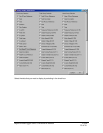
U1-01 = Frequency Reference
U1-02 = Output Frequency
U1-03 = Output Amps
U1-04 = Control Method
U1-05 = Motor speed
U1-06 = Motor Voltage
U1-07 = DC bus voltage
U1-08 = Output Hp
U1-09 = % Torque Output
U1-10 = Input terminal status
U1-11 = Output terminal status
U1-12 = Operation status
U1-13 = Run timer (hours)
U1-14 = Software ID