


User Manual version 2503
LIBRA 120 III (PC620 Intel 815E)
3-23
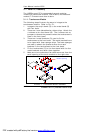
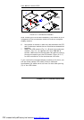
3.1.2. LCD Module Assembly
The following steps illustrate the sequences to assemble the
LCD module. Refer to Fig. 3-2.
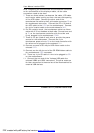
1. Attach the insulator to the invertor (A).
2. Retain the invertor to the LCD holder (C) with two PMS
M3*6 screws. The invertor cable (8) is a 4-pin to 4-pin
cable with wafer connectors at both sides. Connect one
end to invertor first. The other end is to go through the
rectangle opening of the LCD holder to the reverse side
for later connection to motherboard.
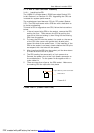
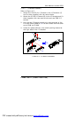
3. The standard LCD used in LIBRA 120 is TORISAN
MXS121022010 or its equivalent. It is a TTL interface
LCD. The LCD cable is a 35 cm DF9-41S to DF13-40
cable. Plug the DF9-41S end to the 41-pin connector at
the rear side of the LCD panel. The DF11-30 end is to
go through the rectangle opening (D) of the LCD
holder to the reverse side for later connection to the
motherboard. MAKE SURE THE LCD JUMPER IS SET PROPERLY
TO THE TTL MODE.
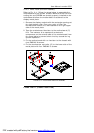
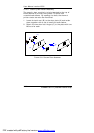
4. Retain the LCD (B) to the LCD holder with four PMS
M3*6 screws.
5. Connect the pink-white wires from the LCD to the
invertor.
PDF created with pdfFactory trial version www.pdffactory.com