


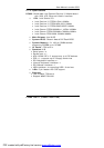

User Manual version 2503
LIBRA 120 III (PC620 Intel 815E)
3-45
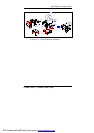
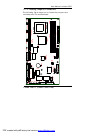
3.3. Kiosk Integration
The panel PC module and Kiosk cabinet module are now
ready for final integration to make a complete Kiosk unit.
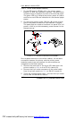
1. Retain the panel PC module to the Kiosk cabinet with four
M4 nuts.
2. Connect the small 4-pin power cable from the power
supply to the CD-ROM board.
3. Plug the ATX power cable from the power supply to the
ATX power connector, ATXP2 on the motherboard.
4. Plug the ATX12V power cable to the ATX12V power
connector, ATXP1 on the motherboard.
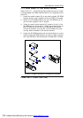
5. Connect the HDD ribbon cable from the motherboard’s
IDE1 to the hard disk drive.
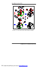
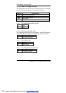
6. Connect the two USB cables to the USB outlets (Fig. 3-14,
3-15 (D)) located at the right side of the cabinet.
7. Plug the cooling fan power connector to the 5V power port
on the I/O board.
8. If a receipt printer is integrated with the Kiosk, plug the
DB25 printer cable from the printer module to the PRT
port on the I/O board.
9. If other peripherals are integrated with the Kiosk, make
sure all the cables and wires are properly connected.
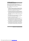
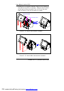
10. Lift the panel PC module upright and leave it ajar from the
Kiosk cabinet. Retain the support bracket located at the
right side of the chassis to the cabinet with one TMS M3*4
screw and one metal washer.
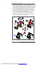
11. Insert the panel PC support bracket (Fig. 3-8, G) into the
bracket catch (Fig. 3-13, E) at the left side of the Kiosk
cabinet. The support bracket can slide in the gutter of the
catch to control the up and down of the panel PC module.
The status of the peripherals inside the cabinet can thus
be monitored.
PDF created with pdfFactory trial version www.pdffactory.com