


User Manual version 2503
LIBRA 120 III (PC620 Intel 815E)
3-38
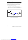
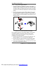
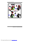
(A)
(B)
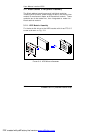
FIGURE 3-12: PRINTER POWER MODULE ASSEMBLY
(C)
3.2.3.2. Printer Power Module Assembly
1. Fix the LED board, LPT-001 (A) to the printer power
bracket (C) with two PMS M3*5 screws. The tack switch
is used to control the back and forth of the thermal paper.
The green LED is to indicate the printer power-on status
and the two red LEDs are indicators for the thermal paper
status.
2. Fix the printer power board, PW-001 (B) to the reverse
side of the power bracket with two PMS M3*5 screws.
The power board is used to transform the panel PC’s 12V
power to 24V to provide necessary power source for the
thermal printer.
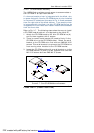
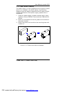
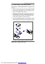
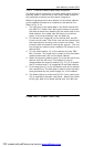
Due to space restriction of the Kiosk cabinet, all the cable
connection between the printer and the printer power
modules needs to be done before the two modules are
integrated to the Kiosk cabinet.
3. Connect the other end of the 6-pin LED cable from the
printer module to CN4 on the LPT-001 board (B).
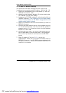
4. Connect the 6-pin wafer connector of the power cable
from the printer module to CN1 on PW-001 board (A).
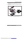
5. There is a Y-shape power cable. Connect the 8-pin wafer
end to CN2 on the PW-001 board.
PDF created with pdfFactory trial version www.pdffactory.com