


User Manual version 2503
LIBRA 120 III (PC620 Intel 815E)
3-40
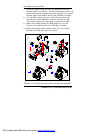
3.2.5. Kiosk Cabinet Integration
The Kiosk cabinet integration of printer bezel model slightly
differs from that of the media reader bezel model.
Before integrating the three modules into the Kiosk cabinet,
some accessories need to be installed to the cabinet first.
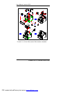
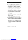
3.2.5.1. LIBRA with printer bezel integration
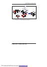
Refer to Fig. 3-14.
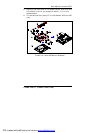
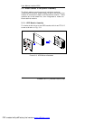
1. The first parts to be assembled to the Kiosk cabinet are
four M8*23.7 rubber feet. Acting as bumpers to prevent
the table surface from abrading by the metal base of the
Kiosk cabinet, the rubber feet are simply to be driven
tightly to the metal cabinet from the base (A).
2. Fix the two butt hinges (B) to the cabinet with two M3
K-lock nuts for each. The K-lock nuts are zinc-plated nuts
with attached free-spinning external teeth lock washer. The
external teeth are used for locking and tension. The two
butt hinges are used to retain the panel PC module to the
cabinet later.
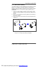
3. Fix the metal bracket (C) to the cabinet with two TMS
M3*4 screws. This metal strip is used to click the plastic
printer bezel (M) into the Kiosk cabinet.
4. Connect the two USB cables to the USB outlets (D)
located at the right side of the cabinet.
5. Retain the support bracket catch (E) to the left side of the
cabinet with two M3 nuts. This bracket is used to
accommodate the support bracket (Fig. 3-8, G) to sustain
the PC module when it is integrated to the Kiosk cabinet.
6. Fix the heat pipe (F) to the left bottom side of the cabinet
with two M3 nuts. The heat pipe is used to direct the cabin
heat generated by the power supply out of the cabinet.
7. The Kiosk cabinet provides one 50*50*10mm cooling fan
(G) to accelerate the cabin ventilation. Attach this cooler
to the right side of the Kiosk cabinet with four M3 nuts.
PDF created with pdfFactory trial version www.pdffactory.com