


User Manual version 2503
LIBRA 120 III (PC620 Intel 815E)
3-36
3.2.3. Printer Module Assembly
The printer module consists of two individual modules, one
printer module and the other printer power module.
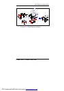
3.2.3.1. Printer Module Assembly
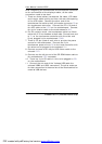
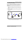
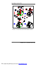
Figure 3-11 illustrates the way to assemble the printer
module.
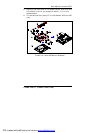
1. Plug the other end of the 6-pin LED cable to C2 on the
printer control board. Plug one end of the big 4-pin
printer power cable to the onboard CN4. Bundle the two
cables together with a plastic clamp.
2. Insert one end of the 21-pin and 15-pin flat cables to CN6
and CN7 on the printer control board BA-T500 (A).
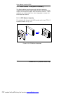
3. Retain the control board to the printer bracket from the
bottom side with four PMS M3*5 screws (B). Make sure
the other ends of the 21-pin and 15-pin flat cables come
out from the rectangle opening at the right side of the
bracket.
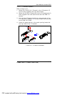
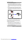
4. Fix the paper tray (F) to the metal bracket (E) with two
M3*2 nuts.
5. Connect the other ends of the 21-pin and 15-pin flat
cables to the printer module (D). Fix the printer module
(D) to the module bracket (E) with four TMS 3*6 screws.
6. Retain the printer module (G) to the printer bracket (B)
with four TMS M3*6 screws. Fix the 21-pin and 15-pin
flat cables on the exterior of the printer bracket (B) with
two nylon cable clips.
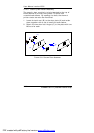
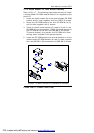
7. Fix the two paper roll brackets (C) to the printer bracket
with two TMS M3*6 screws for each.
8. Insert the spindle (I) to the paper roll (H) and have the
paper roll module put to the paper roll brackets.
9. Align the thermal paper to the paper tray (F) to make sure
the paper would go smoothly into the printer module.
10. Plug the 40-pin end of the printer cable to the printer
module.
PDF created with pdfFactory trial version www.pdffactory.com