


15
Chapter 4
Functional Details
This chapter contains detailed information on all of the features available from the board, including:
a block diagram of board functions
information on how to use, when to use, and when not to use the signals generated by the board
diagrams of signals using default or conventional board settings
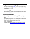
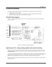
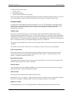
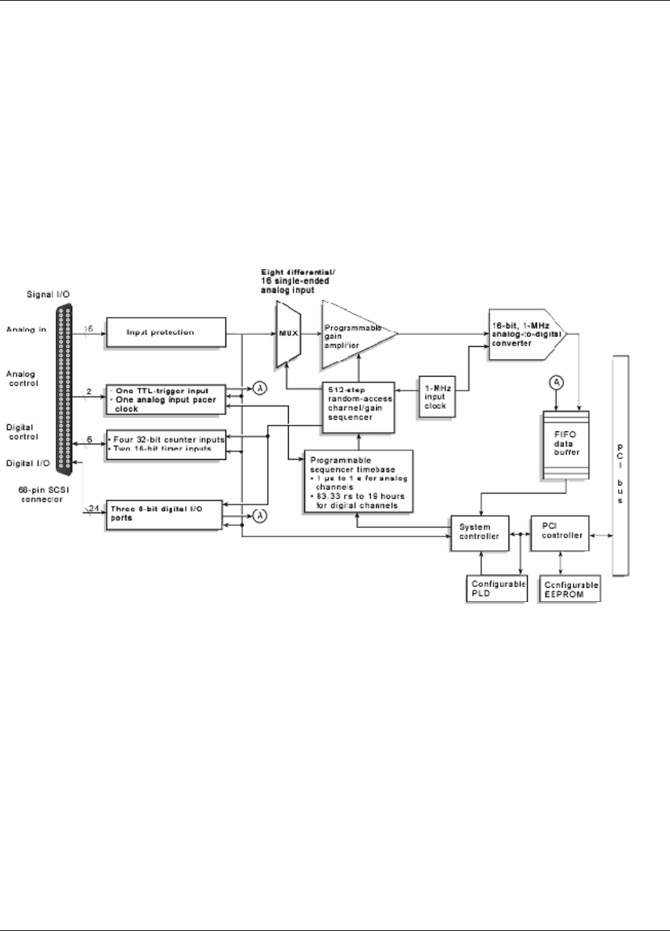
PCI-2513 block diagram
Figure 4-1 is a simplified block diagram of the PCI-2513. This board provides all of the functional elements
shown in the figure.
Figure 4-1. PCI-2513 functional block diagram
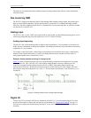
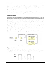
Synchronous I/O – mixing analog, digital, and counter scanning
The PCI-2513 can read analog, digital, and counter inputs, while generating digital pattern outputs at the same
time. Digital and counter inputs do not affect the overall A/D rate because these inputs use no time slot in the
scanning sequencer.
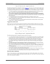
For example, one analog input channel can be scanned at the full 1 MHz A/D rate along with digital and counter
input channels. Each analog channel can have a different gain, and counter and digital channels do not need
additional scanning bandwidth as long as there is at least one analog channel in the scan group.
Digital input channel sampling is not done during the "dead time" of the scan period where no analog sampling
is being done either.