


PCI-2513 User's Guide Specifications
27
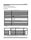
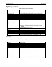
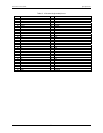
Digital input / output
Table 3. Digital input/output specifications
Number of I/O 24
Ports Three banks of 8.
Each port is programmable as input or output
Input scanning mode Asynchronous, under program control at any time relative to input scanning
Configuration 10 kΩ pull-up to +5 V, 20 pf to analog common
Input protection ±15 kV ESD clamp diodes
Input high +2.0 V to +5.0 V
Input low 0 to 0.8 V
Output high >2.0 V
Output low <0.8 V
Output current Output 12 mA per pin, 200 mA total continuous
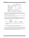
Digital input pacing Onboard clock, external clock (XAPCR)
Digital output pacing Four programmable sources:
Onboard D/A clock, independent of scanning input clock
Onboard scanning input clock
External D/A input clock, independent of external scanning input clock-
(XDPCR)
External scanning input clock-(XAPCR)
Digital input trigger sources and
modes
See Table 6
Digital output trigger sources Start of input scan
Data transfer DMA
Sampling/update rate 12 MHz maximum
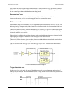
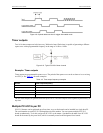
Pattern generation output
Two of the 8-bit ports can be configured for 16-bit pattern generation. The pattern
can also be updated synchronously with an acquisition at up to 12 MHz.
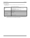
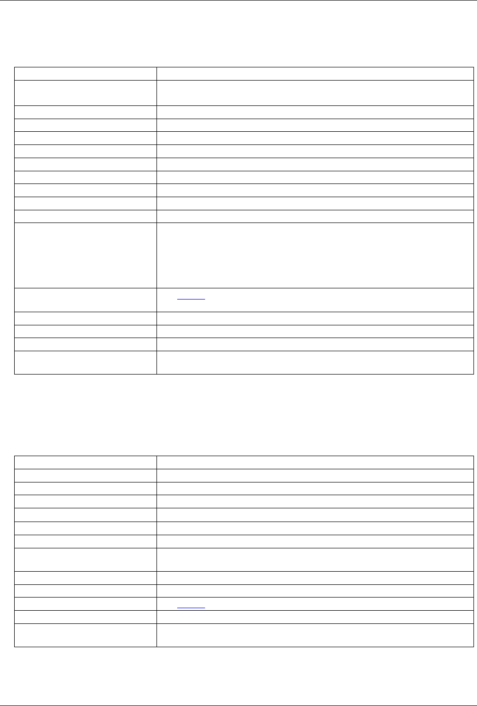
Counters
Counter inputs can be scanned based on an internal programmable timer or an external clock source.
Table 4. Counter specifications
Channels Four independent
Resolution 32-bit
Input frequency 20 MHz maximum
Input signal range -5 V to 10 V
Input characteristics
10 kΩ pull-up, ±15 kV ESD protection
Trigger level TTL
Minimum pulse width 25 ns high, 25 ns low
De-bounce times
16 selections from 500 ns to 25.5 ms, positive or negative edge sensitive, glitch
detect mode or de-bounce mode
Time-base accuracy 30 ppm (0 ° to 50 °C)
Counter read pacer On board clock, external clock (XAPCR)
Trigger sources and modes See Table 6
Programmable mode Counter
Counter mode options
Totalize, clear on read, rollover, stop at all Fs, 16- or 32-bit, any other channel can
gate the counter