


PCI-2513 User's Guide Functional Details
22
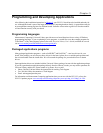
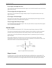
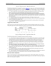
Figure 4-5. Debounce module – trigger after stable mode
The following time periods (T1 through T5) pertain to Figure 4-5. In trigger after stable mode, the input signal
to the debounce module is required to have a period of stability after an incoming edge, in order for that edge to
be accepted (passed through to the counter module.) The debounce time for this example is equal to T2 and T5.
T1 – In the example above, the input signal goes high at the beginning of time period T1, but never stays
high for a period of time equal to the debounce time setting (equal to T2 for this example.)
T2 – At the end of time period T2, the input signal has transitioned high and stayed there for the required
amount of time—therefore the output transitions high. If the input signal does not stabilize in the high state
long enough, no transition would have appeared on the output and the entire disturbance on the input would
have been rejected.
T3 – During time period T3, the input signal remained steady. No change in output is seen.
T4 – During time period T4, the input signal has more disturbances and does not stabilize in any state long
enough. No change in the output is seen.
T5 – At the end of time period T5, the input signal has transitioned low and stayed there for the required
amount of time—therefore the output goes low.
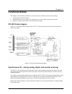
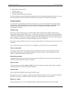
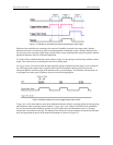
Trigger before stable mode
In the trigger before stable mode, the output of the debounce module immediately changes state, but will not
change state again until a period of stability has passed. For this reason the mode can be used to detect glitches.
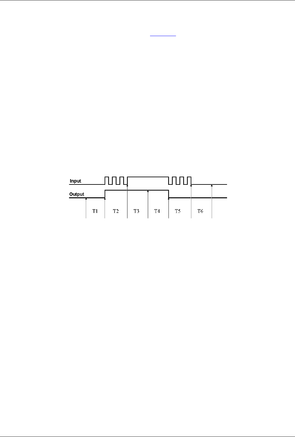
Figure 4-6. Debounce module – Trigger before stable mode
The following time periods (T1 through T6) pertain to the above drawing.
T1 – In the illustrated example, the input signal is low for the debounce time (equal to T1); therefore when
the input edge arrives at the end of time period T1, it is accepted and the output (of the debounce module)
goes high. Note that a period of stability must precede the edge in order for the edge to be accepted.
T2 – During time period T2, the input signal is not stable for a length of time equal to T1 (the debounce
time setting for this example.) Therefore, the output stays "high" and does not change state during time
period T2.
T3 – During time period T3, the input signal is stable for a time period equal to T1, meeting the debounce
requirement. The output is held at the high state. This is the same state as the input.
T4 – At anytime during time period T4, the input can change state. When this happens, the output will also
change state. At the end of time period T4, the input changes state, going low, and the output follows this
action [by going low].
T5 – During time period T5, the input signal again has disturbances that cause the input to not meet the
debounce time requirement. The output does not change state.
T6 – After time period T6, the input signal has been stable for the debounce time and therefore any edge on
the input after time period T6 is immediately reflected in the output of the debounce module.
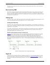
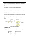
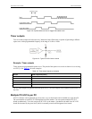
Debounce mode comparisons
Figure 4-7 shows how the two modes interpret the same input signal, which exhibits glitches. Notice that the
trigger before stable mode recognizes more glitches than the trigger after stable mode. Use the bypass option to
achieve maximum glitch recognition.