


PCI-2513 User's Guide Specifications
28
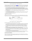
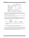
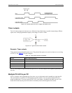
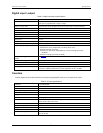
Input sequencer
Analog, digital, and counter inputs can be scanned based on either an internal programmable timer or an
external clock source.
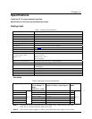
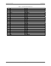
Table 5. Input sequencer specifications
Scan clock sources: two (Note
3Error! Reference source not
found.)
Internal:
Analog channels from 1 µs to 1 sec in 20.83 ns steps.
Digital channels and counters from 83.33 ns to 1 sec in 20.83 ns steps.
External. TTL-level input:
Analog channels down to 1 µs minimum
Digital channels and counters down to 83 ns minimum
Programmable parameters per scan
Programmable channels (random order)
Programmable gain
Depth 512 locations
Onboard channel-to-channel scan
rate
Analog: 1 MHz maximum
Digital: 12 MHz
External acquisition scan clock
input maximum rate
1.0 MHz
Clock signal range: Logical zero: 0 V to 0.8 V
Logical one: 2.4 V to 5.0 V
Minimum pulse width 50 ns high, 50 ns low
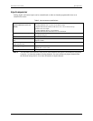
Note 3: The maximum scan clock rate is the inverse of the minimum scan period. The minimum scan period
is equal to 1 µs times the number of analog channels. If a scan contains only digital channels then
the minimum scan period is 83 ns times the number of digital channels.