


PCI-2513 User's Guide Functional Details
24
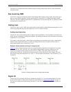
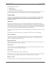
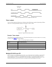
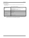
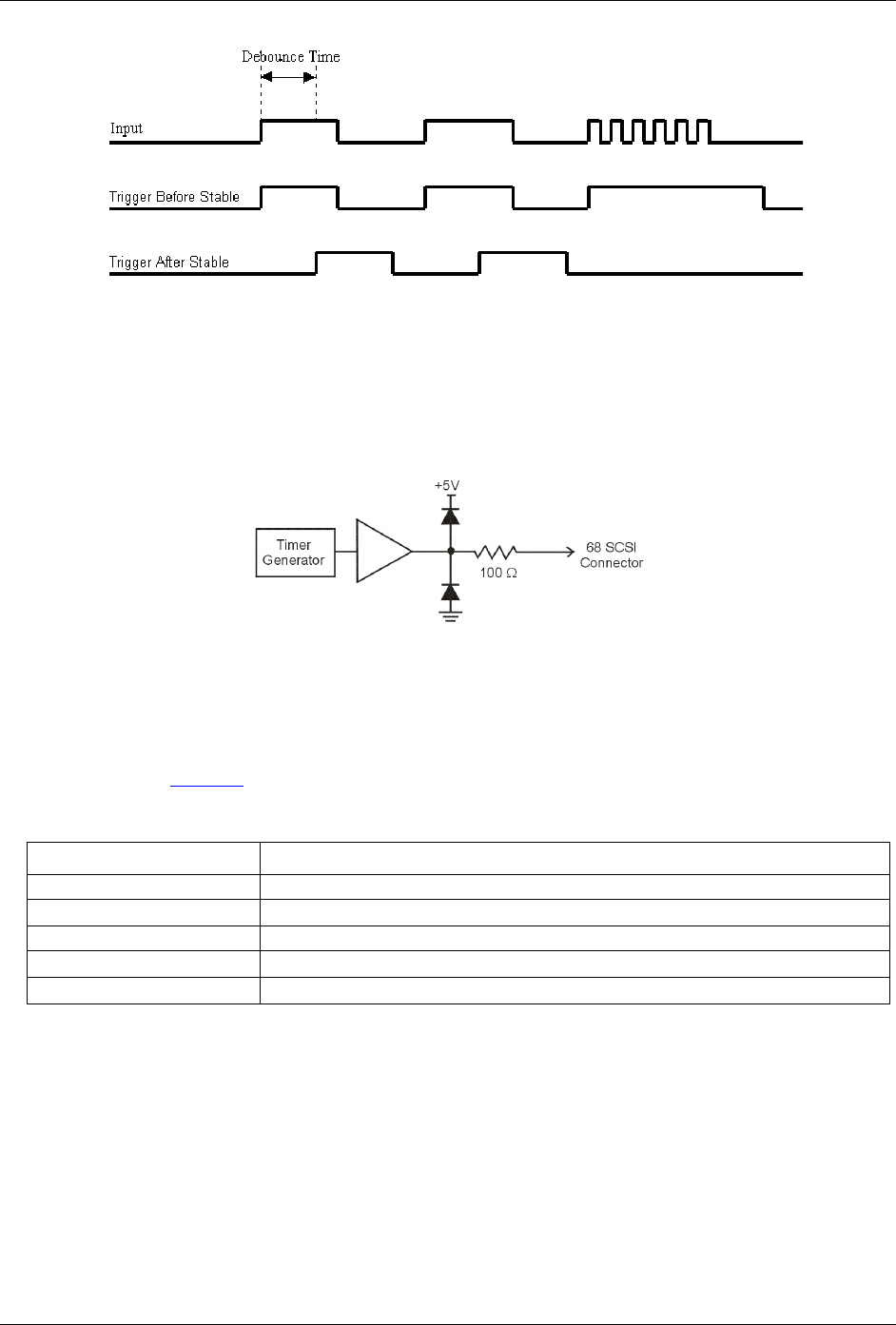
Figure 4-9. Optimal debounce time for trigger after stable mode
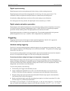
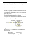
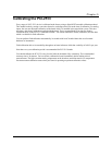
Timer outputs
Two 16-bit timer outputs are built into every 3000 series board. Each timer is capable of generating a different
square wave with a programmable frequency in the range of 16 Hz to 1 MHz.
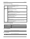
Figure 4-10. Typical PCI-2513 timer channel
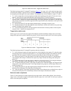
Example: Timer outputs
Timer outputs are programmable square waves. The period of the square wave can be as short as 1us or as long
as 65535 µs. See Table 4-3
for some examples.
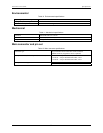
Table 4-3. Timer output frequency examples
Divisor Timer output frequency
1 1 MHz
100 10 kHz
1000 1 kHz
10000 100 Hz
65535 15.259 Hz
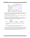
The two timer outputs can generate different square waves. The timer outputs can be updated asynchronously at
any time.
Multiple PCI-2513s per PC
PCI-2513 features can be replicated up to four times, as up to four boards can be installed in a single host PC.
The serial number on each PCI-2513 distinguishes one from another. You can operate multiple PCI-2513
boards synchronously. To do this, assign one PCI-2513 as the master.. Synchronize the other slave PCI-2513
boards to the master by the pacer clock, which is externally routed to the designated slave boards.