


PCI-2513 User's Guide Functional Details
21
Any counter can be gated by the mapped channel. When the mapped channel is high, the counter is enabled.
When the mapped channel is low, the counter is disabled (but holds the count value). The mapped channel can
be any counter input channel other than the counter being gated.
Decrement "on" mode
Sets the counter decrement option to "on" for the mapped channel. The input channel for the counter
increments the counter, and you can use the mapped channel to decrement the counter.
Debounce modes
Each channel's output can be debounced with 16 programmable debounce times from 500 ns to 25.5 ms. The
debounce circuitry eliminates switch-induced transients typically associated with electro-mechanical devices
including relays, proximity switches, and encoders.
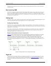
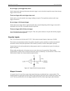
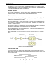
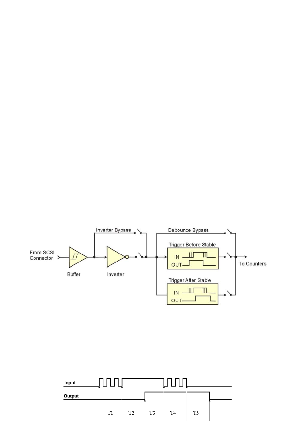
There are two debounce modes, as well as a debounce bypass, as shown in Figure 4-4. In addition, the signal
from the buffer can be inverted before it enters the debounce circuitry. The inverter is used to make the input
rising-edge or falling-edge sensitive.
Edge selection is available with or without debounce. In this case the debounce time setting is ignored and the
input signal goes straight from the inverter or inverter bypass to the counter module.
There are 16 different debounce times. In either debounce mode, the debounce time selected determines how
fast the signal can change and still be recognized.
The two debounce modes are trigger after stable and trigger before stable. A discussion of the two modes
follows.
Figure 4-4. Debounce model block diagram
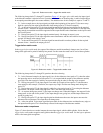
Trigger after stable mode
In the trigger after stable mode, the output of the debounce module does not change state until a period of
stability has been achieved. This means that the input has an edge, and then must be stable for a period of time
equal to the debounce time.