


Meridian 1 3
System reliability
Meridian 1 systems are designed and built to meet the highest standards for
reliability, resulting in less downtime and increased system availability. In
most systems, critical system elements are duplicated to guarantee system
reliability. There are two identical Central Processing Unit (CPU) and
memory circuits in most system configurations, and both CPUs can access
both memory circuits. If one CPU or memory circuit fails, the system
automatically switches to the standby CPU or memory circuit without
disrupting call processing.
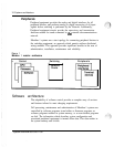
Modular equipment packaging
Meridian
1
hardware is housed in modular equipment cabinets that are
common to all system elements. These cabinets are called Universal
Equipment Modules (UEM). Each UEM has removable front and rear
covers with locking latches for easy access to its contents.
UEMs are stacked one on top of another to form a column. Each column
may contain up to four UEMs. Systems are comprised of one or more
columns. An Expansion Kit is provided to interconnect the columns in a
multi-column system for compliance with FCC standards for EMI/RFI. At
the base of each column of UEMs is the pedestal The pedestal houses
cooling fans, air filters, a power distribution assembly (including the circuit
breakers and power switches) and a System Monitor circuit. At the top of-
each column is a Top Cap assembly which consists of two air exhaust
grilles and a thermal sensor assembly.
Advanced administration
&
maintenance
An important feature common to all Meridian 1 systems is an advanced
administration and maintenance system. Administration and maintenance
functions can be performed locally or at a remote location. These functions
include service change, reassignment of features, and additions or deletions
of equipment. Meridian 1 systems also provide an automatic in-line
conversion feature which significantly simplifies upgrades of Xl 1 software.
Reconfiguration of system data structures occurs during system reload.
A System Monitor circuit card controls and monitors the status of all power-
related hardware and functions, including column thermal status, power
supply operation, blower operation, power fail transfer, circuit breakers,
external rectifiers, batteries, and Uninterruptable Power Supply (UPS)
systems. The same system monitor is used for AC and DC powered
System overview X3-3001 -100
L.
,.
.’