


PRACTICE 553-2201-183
5. OPERATION
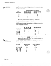
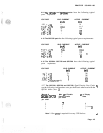
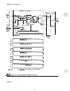
5.01 This part contains signaling and supervision operations which apply
to the line circuit during various states of operation. Refer to Fig. 5-l
for a block diagram of a typical
500/2500
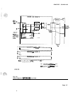
line circuit, Fig. 5-2 for a
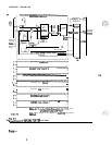
block diagram of the QPC192 and QPC292 packs, and Fig. 5-3 for a
block diagram of the QPC594, QPC729 and QPC789.
c
IDLE CIRCUIT STATE
5.02 The 50012500 Telephone is On-Hook:
No current is drawn from the -48 V supply.
Off-hook detector continuously monitors the state of the
500/2500
line.
In time slot 0, the CE scans each line circuit on the loop in sequence,
detecting any change in signaling on the data input bus.
In time slot 0, the circuit is enabled. Signaling on the data output bus
indicates that the CE is ready to receive data. If no message is
returned from the line circuit to CE, then line circuit is idle.
CALL ORIGINATED
FROM A 50012500
TELEPHONE
5.03 Originating the Call.
(1)
Telephone goes off-hook.
(2)
Current is drawn from the -48 V supply.
(3) Off-hook state is detected by off-hook detector.
(4)
Multiplex control sends off-hook signaling to CE on data input-bus
during time slot 0 (via the buffer).
(5) CE detects signaling from line circuit and determines circuit
number (terminal number).
(6)
C$
assigns message time slot to line circuit (from time slots 2 to
(7) The line circuit and PCM
codec
are enabled during the message
time slot assigned to the line circuit.
(8)
CE applies dial tone (during message time slot) to telephone via
data output bus, multiplex control, digital-to-analog filter and
hybrid transformer.
(9) Dialed information from telephone is applied to data input bus
during time slot 0 (signaling).
(10)
CE detects dialing and removes dial tone at start of dialing.
(11)
CE decodes dialed information.
Page
5-l
8 Pages