


48 Planning the site
-
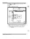
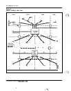
The building cable plan
The building cable plan should be divided into zones.
The zones are
typically the termination point of conduits throughout the office. Each zone
on the building cable plan should be identified with a letter or number, and a
block of numbers should be assigned to each zone. Be sure to leave room
for expansion. See Figure 8 “Sample building cable plan” for an illustration
of zoning.
In addition, the following information and guidelines should be consider&
Each telephone, console, or data set connected to the SL-1 requires
telephone wire run from a nearby telephone jack to a cross-connect
location. Also, each component connected to the system requires a
termination. (Modular jacks should be within 8 ft
[2436 mm] of the device.) The location of all devices that interface
with the SL- 1 should be known.
Telephone directory number, features, and Office Data Administration
System (ODAS) designator of each telephone in the office should also
be known.
-
Three-pairs of telephone wire should be provided from the telephone or
data set location to the distribution frame. Location of all distribution
points (main and intermediate) should be known.
Consoles require a 16-pair (or
25pair)
cable equipped with an
Amphenol-type connector.
If any existing wire is to be used, ownership of that wire must be
clearly defined.
All wiring carrying high-speed data must pass a verification test at the
time of installation. The test is performed as part of the installation
procedures.
Installation planning 553-3001-120
-..
:.:;
.\
--.;.,:.j
:
:
.,
.
..‘-
a
.